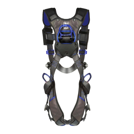
DBI SALA 2200406 사용자 지침 - 페이지 5
{카테고리_이름} DBI SALA 2200406에 대한 사용자 지침을 온라인으로 검색하거나 PDF를 다운로드하세요. DBI SALA 2200406 12 페이지.

If the connecting element that a snap hook (shown) or carabiner attaches to is undersized or irregular in shape,
a situation could occur where the connecting element applies a force to the gate of the snap hook or carabiner.
This force may cause the gate (of either a self-locking or a non-locking snap hook) to open, allowing the snap
hook or carabiner to disengage from the connecting point.
1. Force is applied to the
snap hook.
NOTE: Large throat opening snap hooks should not be connected to standard size D-rings or similar objects which will
result in a load on the gate if the hook or D-ring twists or rotates. Large throat snap hooks are designed for use on fixed
structural elements such as rebar or cross members that are not shaped in a way that can capture the gate of the hook.
C. In a false engagement, where
features that protrude from the
snap hook or carabiner catch on
the anchor and without visual
confirmation seems to be fully
engaged to the anchor point.
D. To each other.
E. Directly to webbing or rope
lanyard or tie-back (unless the
manufacturer's instructions for
both the lanyard and connector
specifically allow such a
connection).
F. To any object which is shaped or
dimensioned such that the snap
hook or carabiner will not close and lock, or that roll-out could occur.
2.4 ANCHORAGE STRUCTURE: The anchorage structure must be rigid and capable of supporting at least 2,800 lbs.
(12.4 kN) along the axis of the horizontal lifeline. Anchorages must also support at least 2,800 lbs. (12.5 kn) applied
in all potential directions of fall arrest that are perpendicular to the axis of the horizontal lifeline. See Figure 5.
2.5 CONNECTING SUBSYSTEM: The connecting subsystem is the portion of the personal fall arrest system that
connects the horizontal lifeline subsystem to the harness fall arrest attachment element. A DBI/SALA Force 2
Energy Absorbing Lanyard must be used as the connecting subsystem with the Vacuum Anchor Horizontal Lifeline.
3.0 OPERATION AND USE
WARNING: Do not alter or intentionally misuse this equipment. Consult DBI/SALA when using this equipment in
combination with components or subsystems other than those described in this manual. Some subsystem and component
combinations may interfere with the operation of this equipment. Use caution when using this equipment around moving
machinery, electrical hazards, chemical hazards, and sharp edges.
Figure 3 - Unintentional Disengagement (Roll-out)
Small ring or other
non-compatibly
shaped element
2. The gate presses against
the connecting ring.
3. The gate opens allowing the
snap hook to slip off.
Figure 4 - Inappropriate Connections
5
