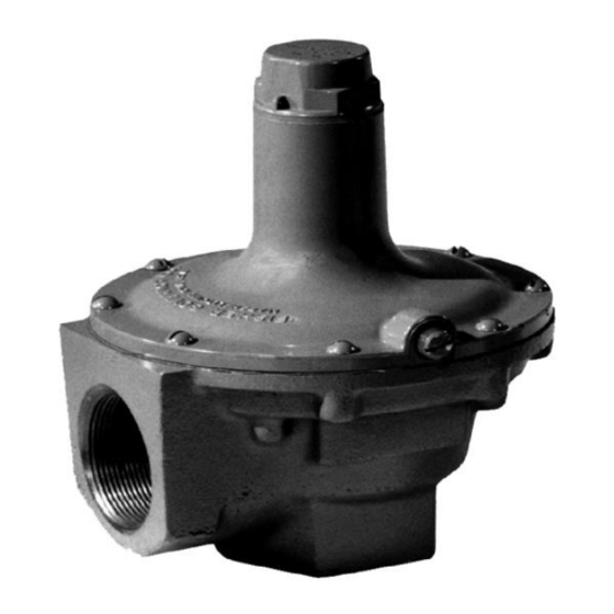
Emerson 289 Series 사용 설명서 - 페이지 4
{카테고리_이름} Emerson 289 Series에 대한 사용 설명서을 온라인으로 검색하거나 PDF를 다운로드하세요. Emerson 289 Series 11 페이지.

289 Series
service
regulator
AJ4698-C
A2404-1
For 2 NPT Type 289H relief valves, when changing from
one spring range to another, it is recommended that a
new spring case be used so that the travel stop drive
screw will be positioned correctly for the corresponding
spring range. Each spring range requires that the travel
stop drive screw be positioned appropriately in the spring
case to prevent setting the relief valve pressure too high.
The location of the travel stop drive screw for each spring
and spring range is shown in Figure 5.
Shutdown
Close the upstream shutoff valve and release
all pressure from the relief valve.
Maintenance
Relief valve parts are subject to normal wear and
should be inspected periodically for maintenance. The
frequency of inspection and replacement of parts
depends upon the severity of service conditions.
This section contains information for inspection
and maintenance of 289 Series relief valves.
4
บริ ษ ั ท เอดี ด ี เฟอร์ เ นส จ ำกั ด
ADD FURNACE CO.,LTD.
44 ซอยบรมราชชนนี 70 ถนนบรมรำชชนนี แขวงศำลำธรรมสพน์ เขตทวี ว ั ฒ นำ กรุ ง เทพฯ 10170
โทร: 02-888-3472 โทร: ออกแบบ
08-08-170-170
:
https://www.add-furnace.com E-mail:
Figure 4. Typical Installation
แฟกซ์ : 02-888-3258
protect vent pipe
with rain cap
Maintenance procedures are presented for relief valve
configurations of similar construction. Refer to the
appropriate procedure and Figure for the particular
relief valve configuration when changing the control
spring to one of a different range or when inspecting,
cleaning or replacing any other relief valve parts. The
screen (key 9, Figures 6 through 9) and vent piping, if
present, should be free of foreign material that might
impair relief flow.
It is recommended that a good quality pipe thread
sealant be applied to pressure connections and fittings
and a good quality lubricant be applied to all O-rings.
Also apply an anti-seize compound to the adjusting
screw threads and other areas as needed. Reference
Figures 6 through 10 to determine the recommended
lubricant/sealant/adhesive for these parts. All
lubricants/sealants/adhesives must be selected such that
they meet the temperature requirements.
Note
The relief valve body (key 1, Figures 6
through 10) may remain in the pipeline
during maintenance unless replacement
of the valve body is necessary.
289 Series
relief valve
