Galaxy DX 44HP 소유자 매뉴얼 - 페이지 5
{카테고리_이름} Galaxy DX 44HP에 대한 소유자 매뉴얼을 온라인으로 검색하거나 PDF를 다운로드하세요. Galaxy DX 44HP 10 페이지. 10 meter amateur mobile transceiver
Operation
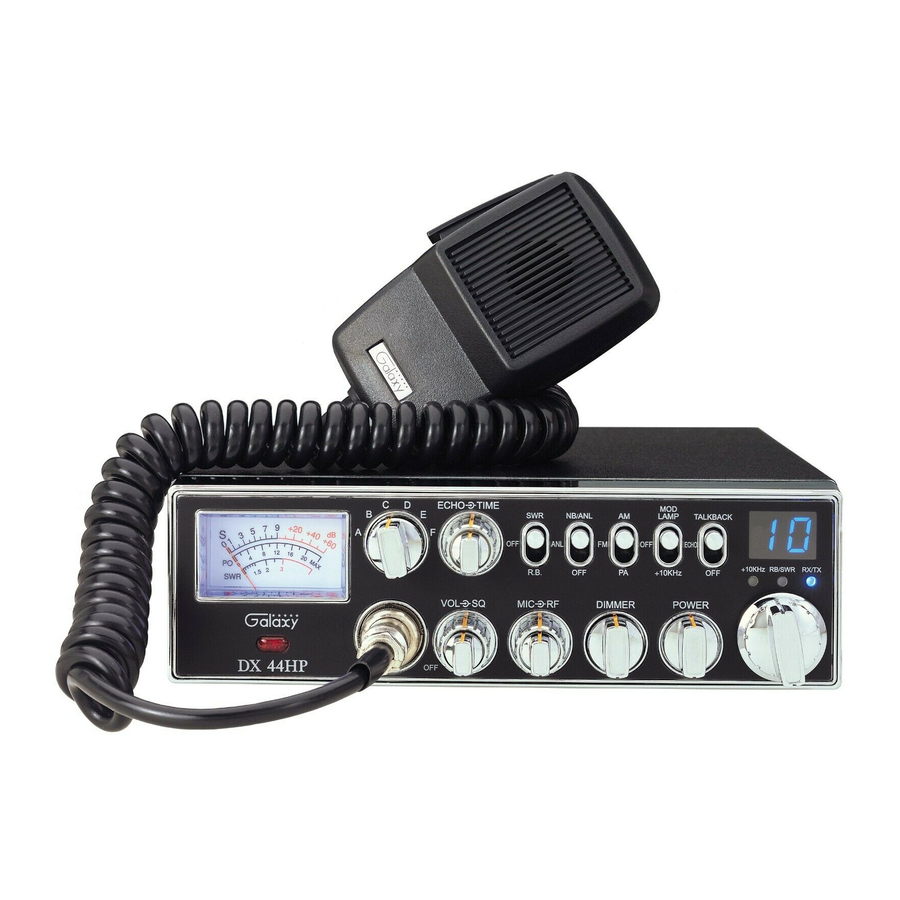
CONTROL FUNCTIONS
There are fifteen controls and six indicators on the front panel of your
transceiver.
FRONT PANEL
1.
MOD LAMP: When switched on, this Modulation indicator will illuminate as
you speak into the microphone. When you speak louder, it appears bright
because it is on nearly 100 percent of the time and when you speak softer, it
appears dimmer because it is flickering on and off. It does not glow at all when
there is no modulation. This lamp operates in all modes.
2.
MICROPHONE JACK: Used to connect microphone for voice source.
3.
SQUELCH CONTROL (outer dual concentric): This control is used to cut
off or eliminate receiver background noise in the absence of an incoming
signal. For maximum receiver sensitivity it is desired that the control be
adjusted only to the point where the receiver background noise or ambient
background noise is eliminated. Turn fully counterclockwise then slowly
clockwise until the receiver noise disappears. Any signal to be received must
now be slightly stronger than the average received noise. Further clockwise
rotation will increase the threshold level which a signal must overcome in
order to be heard. Only strong signals will be heard at a maximum clockwise
setting.
4.
OFF/ON/VOLUME CONTROL (inner dual concentric): Turn clockwise to
apply power to the unit and to set the desired listening level. During normal
operation, the VOLUME control is used to adjust the output level obtained
either at the transceiver speaker or the external speaker, if used.
-7-
5.
RF GAIN CONTROL: (outer dual concentric). Use to reduce the gain of
the received signal under strong signal conditions.
6.
MIC GAIN CONTROL: (inner dual concentric). Adjust the microphone
gain in transmit and PA modes. This controls the gain to the extent that full
talk power is available several inches away from the microphone.
7.
DIMMER CONTROL: Controls the brightness of the meter lamp, channel
display digits, +10KHz LED, RB LED and the RX/TX LED. It does not
control the brightness of the SWR alert LED. That LED is always at maximum
brightness.
8.
RF POWER CONTROL: This control allows the user to adjust RF power
output.
9.
CHANNEL SELECTOR: This switch selects any one of the forty channels
desired. The selected channel number is on the LED readout directly above the
Channel Selector knob.
10. RX/TX LED: This LED lights red to indicate the unit is in the transmit mode.
It lights blue to indicate the unit is in the receive mode.
11. METER: Indicates received signal strength, transmitter output power and
SWR.
12. BAND SELECTOR: This switch is used to select the band.
13. TIME CONTROL: (outer dual concentric). This control is used to set the
interval of the echo effect.
14. ECHO CONTROL: (inner dual concentric). This control is used to set the
amount of the echo effect.
15. SWR/OFF/R.B. SWITCH: This switch controls the function of the meter
during the transmit mode. In the "SWR" position, the meter indicates the
Standing Wave Ratio (SWR) of your antenna (accurate at maximum power
output). There are no adjustments because the SWR circuit in this radio
calibrates itself automatically. When in the RB position, the radio transmits an
audio tone at the end of your transmission to indicate that transmission has
ended. As a courtesy to others, use the Roger Beep only when necessary. The
SWR function and the RB function cannot be used at the same time.
- 8-