dbx 160X 사용 설명서 - 페이지 6
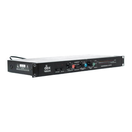
{카테고리_이름} dbx 160X에 대한 사용 설명서을 온라인으로 검색하거나 PDF를 다운로드하세요. dbx 160X 8 페이지. Professional single-channel
compressor/limiter
dbx 160X에 대해서도 마찬가지입니다: 사용 설명서 (17 페이지)
3.4 STEREO STRAPPING
Two channels of program material do not
necessarily constitute a stereo program. A stereo
program is one where the two channels are
recorded and/or mixed to create the illusion
of a sir)gle, unified "panorama" of sound. The
stability of the psychoacoustic "image'' of each
sound source within the stereo program depends
upon·its ability to maintain a specific phase and
amplitude relationship from left to right channel.
If two independent compressors are used
to
process the stereo program, a loud sound occurring
in one channel will cause a gain reduction only in
that channel. This gain reduction would cause the
perceived image of any sound spread between the
two channels to move toward the side which had
not been compressed, because the
spread
signal
would be momentarily softer in the compressed
channel. This can be avoided by linking the two
compressors in such a
way
that both channels
receive the same amount of compression -
an
amount equal to the maximum
''needed''
by
either channel at that moment. On the 160X,
this is accomplished by means of
the
STRAPPING jacks; a cable between these
jacks permits the RMS detectors of both
-
units
to "talk" to one another - but only when one
of the units' SLAVE buttons is
depressed.
Each
compressor then senses the incoming signal
level, which is compared to
the
threshold set on
the master (the unit whose SLAVE button is
not
depressed). If the comprealon
Is ;equired
by
either channel, both channels are a,bject to
compression - the same amount of it - so
the
stereo image remains stable.
When compressing
a stereo
program with a pair
of 160Xs, only the master unit controls need be
adjusted.
12
3.5 METER CALIBRATION
The INPUT/OUTPUT LEVEL DISPLAY in thr
160X is factory.calibrated
to
indicate "O" when
the signal level is +4 dBm (1.23 V) at either the
input or output of the 180X, depending on the
DISPLAY function switch position. (The
METER CALIBRATION control does not affect
the -GAIN CHANGE LEDs.)
·
.
To
recalibrate the
LEVEL DISPLAY, depress
the DISPLAY button
to
meter the INPUT LEVEL,
and
feed
a
1 kHz
signal at the selected
nominal
operating level
(the
level desired for a ''O dB"
meter indication)
to
the
180X's SIGNAL INPUT.
Then adjust
the
rear panel METER CALIBRA-
TION control until the meter indicates ''O dB."