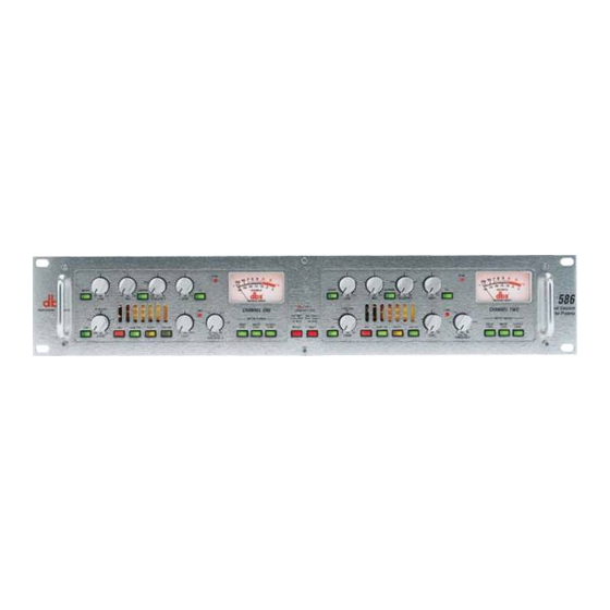
dbx 586 소유자 매뉴얼 - 페이지 9
{카테고리_이름} dbx 586에 대한 소유자 매뉴얼을 온라인으로 검색하거나 PDF를 다운로드하세요. dbx 586 16 페이지. Vacuum tube preamplifier

Op p era a t t ing Co o nt t ro o ls s
FRONT PANEL
0
0
INSERT
-15
+15
-15
+15
dB
dB
LOW
MID
(LINE 0dB)
+25
+15
+30
LINE
+48V
20 dB PAD
-10
+60
dB
DRIVE
INSERT switch
This switch enables the rear-panel insert loop by inserting any device connected to the Send and Return
jacks into the signal path. The insertion point is post-tube, pre-EQ.
LOW control
This control varies the gain of the low frequency equalization; the gain range is -15 to +15 dB. The low
frequency filter is a shelving lowpass configuration with a knee frequency of 80 Hz.
MID control
This control varies the gain of the mid frequency equalization; the gain range is -15 to + 15 dB. The mid
frequency filter is a bandpass configuration with variable frequency and switchable bandwidth.
NARROW switch
This switch selects the bandwidth for the mid frequency filter. The default bandwidth is 1.5 octaves; with
the NARROW switch depressed, the bandwidth is 0.5 octaves.
Power Supply, if required
1k
0
PEAK
20 10
200
4k
-
NARROW
EQ
-30
100
8k
-15
+15
Hz
dB
FREQUENCY
HIGH
0
LIMIT
+10
+15
+5
+20
DRIVE
INVERT
LOW CUT
LEVEL
-15
+15
0
Off
dB
dBu
LEVEL
PeakPlus
THRESHOLD
MANUFACTURED UNDER THE FOLLOWING U.S. PATENTS:
4,368,425 5,282,252. OTHER PATENTS PENDING.
Channel 1
IN
0
7 5 3
0 3
+
INSERT
-20
-15
-10
-25
-5
DECIBELS
0
-15
dB
¨
LOW
TYPE IV
(LINE 0dB)
CONVERSION SYSTEM
CHANNEL ONE
+25
Red: SNR
2
Red: Shape 2
Green: TPDF Green: Shape 1
METER SOURCE
+15
Off: None
Off: None
INSERT
OUTPUT
LEVEL
LEVEL
DITHER
SHAPE
LINE
-10
dB
DRIVE
OUT
Figure 2: Connecting the 586 to a recorder
0
1k
0
200
4k
NARROW
EQ
+15
-15
+15
100
8k
-15
+15
dB
Hz
dB
MID
FREQUENCY
HIGH
0
LIMIT
+10
+30
+5
+48V
20 dB PAD
INVERT
LOW CUT
+60
-15
+15
dB
LEVEL
586
PEAK
7 5 3
0 3
20 10
-
+
-20
-15
-10
-25
-5
DECIBELS
-30
0
¨
586
Dual Vacuum
CHANNEL TWO
+15
Tube Preamp
METER SOURCE
+20
DRIVE
INSERT
OUTPUT
LEVEL
LEVEL
LEVEL
0
Off
dBu
PeakPlus
THRESHOLD
7
