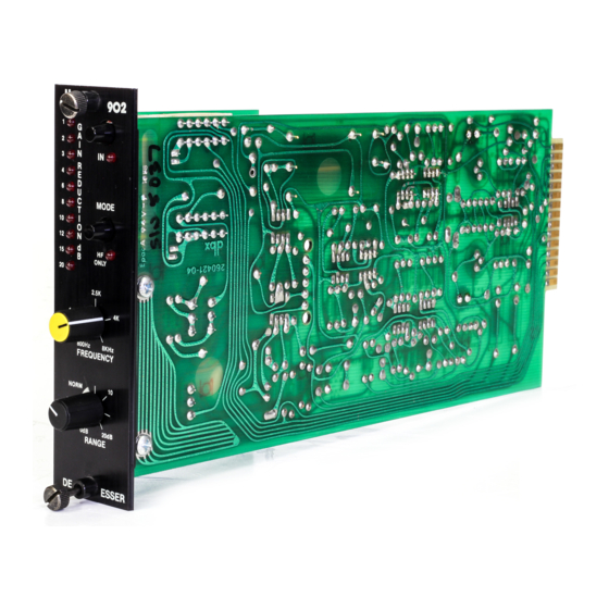
¨
902
We suggest saving the shipping carton and packaging materials for safely transporting your 902 in the future.
Packed in the carton you should find the following:
¥ 902 unit
¥ operations manual (this is it)
¥ warranty registration card
Take the time now to fill out your warranty registration card and send it to us.
C
ONNECTING THE
Terminating resistors are not necessary for the 902Õs audio input to provide proper operation, but they may be
required if the input is fed from a device designed for a specified load impedance, such as a passive equalizer. The
902 has an actual input impedance of 20 k½ in balanced mode and >10 k½ if unbalanced. This makes the 902
audio input suitable for use with virtually any source impedance, low or high.
B
ALANCED
If you are using the F900A mainframe, connect the signal leads to the A+ and A- terminals; if you are using an
FS900 miniframe, connect the hot (+) signal lead to pin 3 of the XLR connector, and the cold (-) signal lead to pin 2
of the XLR connector. For custom installations refer to the 902 diagram in Figure 1. If hum develops, try attaching
the shield to the ground connection at the 902 input.
U
NBALANCED
If you are using an F900A mainframe, wire the hot lead to the A+ terminal, and the shield to the A- terminal; if you
are using an FS900 miniframe, wire the hot lead to pin 3 of the XLR connector, and wire the shield to pin 2 of the
XLR connector. For custom installations refer to the 902 circuit board diagram in figure 1. If hum develops, try con-
necting a jumper between the A- terminal and the 902Õs input ground. Reversing the wires to the input terminals will
result in the output signal from the 902 being 180 degrees out of phase with the input signal.
Figure 1: 902 Audio
Connections
For maximum hum rejection avoid common grounding at the 902Õs input and output. The best starting point is to
ground the shield of the input cable at the source device, leaving it unconnected to the 902, and to ground the
shield of the output cable to the ground terminal of the 902, leaving it unconnected at the receiving device.
C
A
O
ONNECTING THE
UDIO
UTPUTS
The output of the 902 is designed to feed balanced or unbalanced loads of 600 ½ or greater. The output stage is
single-ended; in normal operation the B- terminal is connected internally to the circuit ground. When the bypass
switch is engaged, the signal inputs are directly connected to the signal output (i.e. A+ to B+, and A- to B-) and the
internal jumper between B- and the circuit ground is removed.
The IN/OUT switch on the 902 introduces no noise into the signal path when it is switched. Switching back and forth
between processed and unprocessed signal may reveal a level difference, depending upon the degree to which the
program material is being de-essed. If a pop or click is apparent when the IN/OUT switch is activated, there is prob-
ably a grounding problem in the signal processing system. Compare the grounding of the signal shields to and from
902
TO YOUR AUDIO SYSTEM
Audio Balanced Inputs
Ground
Audio Unbalanced Output
(Balanced Bypass)
F900A Mainframe
Connections
Out
Control
Voltage
In
FS900 Miniframe Rear Panel
2
A
A
1 -24V
2 +24V
3 Front Panel Ground
4 Circuit Ground
5 +15V
6 -15V
7 N/C
B
8 N/C
9 CV IN
10 CV OUT
11 Circuit Ground
12 A+
C
13 A-
14 B+
15 B-
D
dbx 902 Circuit Board
B
C
D
1
R74
}
Bal Audio
15
Input
902
}
Bal Audio
Output
FEMALE
-2
1
A, C
+3
1
-2
B, D
+3
MALE
3
