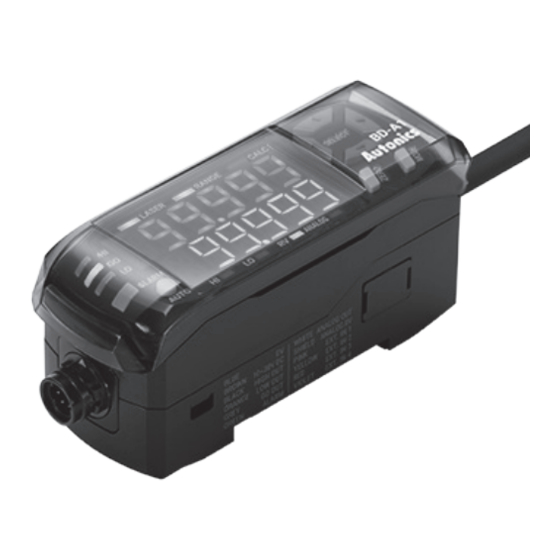
Autonics BD Series 제품 설명서 - 페이지 3
{카테고리_이름} Autonics BD Series에 대한 제품 설명서을 온라인으로 검색하거나 PDF를 다운로드하세요. Autonics BD Series 5 페이지. Laser displacement sensors amplifier unit
Autonics BD Series에 대해서도 마찬가지입니다: 매뉴얼 (14 페이지), 제품 설명서 (6 페이지), 제품 설명서 (3 페이지)

Installation Step 3. Precautions for Mounting Sensor Head
Install the sensor head to minimize measurement error for stable measurement.
■ Moving object measurement
Correct
Wrong
■ Narrow area or concave object
Correct
Wrong
■ Wall mounting
Correct
Wrong
■ Black object
Example
Installation Step 4. Mounting
■ Sensor head
Bolts
Nuts
Emission
center line
■ Accessory: Ferrite core
Description
Object with material / color
difference
Install the emitter and receiver in
parallel to the material or color
boundary of the object.
Rotating object
Install the receiver and the rotating
shaft in parallel to minimize the
influence of fluctuations and
position deviations.
Object with step
Install the emitter and receiver
vertically to the line between crest
and valley of the object.
Description
Install the sensor head where the
reflected laser beam does not
blocked toward the receiver part.
Description
Install the sensor head where the
reflected laser beam from the wall
does not enter the receiver part. If
the color of wall is black with low
reflectivity and no gloss, the error
can be minimized.
Description
When measuring black object with
low reflectance the amount of
light received decreases, install the
sensor head closely to the object.
• Mount to the panel directly or through the
bracket by using bolts and nuts.
Tightening
Model
Bolt
torque
BD-030 / 065 / 100
M3
0.5 N m
BD-300 / 600
M4
0.6 N m
• Install the measurement object and the center
line are in a straight line. Check the mounting
position considering emission center line,
vibration and shock.
• Within 30 mm from the sensor head, wind the
cable through the inside of the ferrite core
three times and mount the ferrite core.
Dimensions
• Unit: mm, For the detailed dimensions of the product, follow the Autonics web site.
A
Optical axis of emitter
■ BD-030
38
22
4
A
8.6
19.5
Ø4.2, 0.5 m
■ BD-065 / 100
42.5
25.3
4.5
A
9.1
22.5
Ø4.2, 0.5 m
■ BD-300 / 600
56.5
31.9
14.9
4.8
13.95
Ø4.2, 0.48 m
■ Ferrite core
32
Unit Descriptions
• It describes based on BD-030.
1. Laser receiver
Receives the laser reflected from the measurement target.
2. Laser emitter
The point at which a laser is projected on a target to
measure displacement.
1
3. Emission center line
The line and the object should be aligned because the
2
laser is emitted along the line.
3
Install the measurement object and the center line are in a
straight line.
4. Power indicator (POWER, red)
Indicates whether the sensor head is powered or not.
5. Laser emission indicator (LASER, green)
4
5
Turns ON while the laser is emitted from the sensor head.
6. NEAR/FAR indicator (NEAR/FAR, green)
6
Flashes outside the rated measurement range and turns
ON near the reference distance .
• For more information about indicators, refer to the
Installation Step 2. Selecting Sensor Head Mounting
Location
Fixing bracket (BK-BD-A)
54
Ø3.2
43
2-Ø3.2
R1.5
4-R1.6
2-R1
2-R3
9.2
Fixing bracket (BK-BD-B)
60.5
40.5
Ø3.2
2-R3
48.5
2-Ø3.2
R1.5
4-R1.6
2-R1
2-R3
8.85
Fixing bracket (BK-BD-D)
82
53
Ø4.4
2-R2.2
2-R5
66.4
A
2-Ø4.4
4-R2.2
2-R5
20
1.6
25
1.6
28.6
R0.5
1.6
