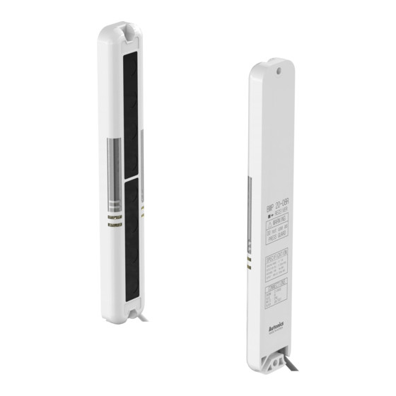
Autonics BWP20-12 빠른 시작 매뉴얼 - 페이지 3
{카테고리_이름} Autonics BWP20-12에 대한 빠른 시작 매뉴얼을 온라인으로 검색하거나 PDF를 다운로드하세요. Autonics BWP20-12 5 페이지.

Specifications
Model
BWP20-08(P)
Sensing method
Through-beam
Light source
Infrared LED (850 nm modulated light)
Sensing distance
0.1 to 5.0 m
Sensing target
Opaque material
Min. sensing target
≥ Ø 30 mm
Number of optical axes 8
Sensing height
140 mm
Optical axis pitch
20 mm
Response time
≤ 6 ms (frequency B: ≤ 7 ms)
Operation mode
Light ON / Dark ON (switch)
Functions
Emitter OFF, operation mode change, Job indicator ON / flashing
Interference protection Interference protection by transmission frequency selection
Synchronization type
Timing method by synchronous line
Emitter: frequency A indicator (green), frequency B indicator (yellow)
Indicator
Receiver: operation indicator (red), stable indicator (green)
Emitter / receiver: Job indicator (red)
Approval
ᜢ ᜫ
≈ 280 g
Weight (packaged)
(≈ 480 g)
Power supply
12 - 24 VDCᜡ (ripple P-P: ≤ 10 %)
Current consumption
Emitter / receiver: ≤ 80 mA
Control output
NPN / PNP open collector output model
Load voltage
≤ 30 VDCᜡ
Load current
≤ 150 mA
Residual voltage
NPN: ≤ 1 VDCᜡ, PNP: ≤ 2.5 VDCᜡ
Reverse power protection circuit, output short overcurrent
Protection circuit
protection circuit
Insulation resistance
≥ 20 MΩ (500 VDCᜡ megger)
± 240 V the square wave noise (pulse width: 1㎲) by the noise
Noise immunity
simulator
Dielectric strength
1,000 VACᜠ 50 / 60 Hz for 1minute
1.5 mm double amplitude at frequency of 10 to 55 Hz (for 1 min)
Vibration
in each X, Y, Z direction for 2 hours
Shock
500 m/s² (≈ 50 G) in each X, Y, Z direction for 3 times
Ambient illumination
Ambient light: ≤ 100,000 ㏓
(receiver)
Ambient temperature
-10 to 55 ℃, storage: -20 to 60 ℃ (no freezing or condensation)
Ambient humidity
35 to 85 %RH, storage: 35 to 85 %RH (no freezing or condensation)
Protection rating
IP40 (IEC standard)
Cable spec.
Ø 3.5 mm, 4-wire, 3 m
Wire spec.
AWG 24 (0.08 mm, 40-core), insulator diameter: Ø 1 mm
Material
Case: PC / ABS, sensing part: PMMA
Troubleshooting
Malfunction
Cause
Power supply
Cable incorrect connection, or
Non-operation
disconnection
Out of rated sensing distance
Pollution by dirt of sensor cover
Non-operation in
sometimes
Connector connection failure
Out of the rated sensing distance
There is an obstacle to cut off the
Control output is
emitted light between emitter and
OFF even though
receiver.
there is not a target
There is strong electric wave or
object.
noise generator such as motor,
electric generator, or high voltage
line, etc.
Synchronous line incorrect
connection or disconnection
LED displays for
synchronous line
Break of synchronous circuit of
emitter or receiver
Control output line is shorted out. Check the wiring connection.
LED displays for
over current
Over load
BWP20-12(P)
BWP20-16(P)
BWP20-20(P)
12
16
20
220 mm
300 mm
380 mm
ᜢ ᜫ
≈ 320 g
≈ 360 g
≈ 430 g
(≈ 520 g)
(≈ 620 g)
(≈ 680 g)
Troubleshooting
Supply the rated power.
Check the wiring connection.
Use it within rated sensing distance.
Remove dirt by soft brush or cloth.
Check the assembled part of the
connector
Use it within the rated sensing
distance.
Remove the obstacle.
Put away the strong electric wave
or noise generator.
Check the wiring connection.
Contact Autonics Corp.
Check the rated load capacity.
Functions
■ Interference protection (transmitted light frequency change)
When you install more than two products, there is a risk of mutual interference.
Change the frequency to prevent this interference. Set one sensor as frequency A and
the other as frequency B via the setting switch.
■ Emitter OFF
When 0 V is applied to the TEST input of the emitter, the light emission is forcibly
stopped and the external system can check whether the sensor is operating normally.
When the emission is stopped, the light is blocked. In the case of Light ON mode, the
control output turns OFF. In the case of Dark ON mode, the control output turns ON.
The red LED of the emitter flashes until the TEST input is released.
• Control output pulse by TEST input
ON
Setting switch
OFF
T
T
1
1
T
Control output
ON
2
(Light ON)
OFF
Normal
■ Operation mode change (Light ON / Dark ON)
It is available to select with user's preference.
- Light ON: The control output is ON when it is light ON
- Dark ON: The control output is ON when it is light OFF
■ Job indicator (ON / flashing)
Job indicator is lighting or flashing to make out work sensing operation more easily.
T
≥ 50 ms
1
T
2
T
≥ 50 ms
2
Abnormal
