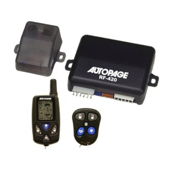
Autopage RF-420LCD 설치 매뉴얼 - 페이지 5
{카테고리_이름} Autopage RF-420LCD에 대한 설치 매뉴얼을 온라인으로 검색하거나 PDF를 다운로드하세요. Autopage RF-420LCD 12 페이지. Professional vehicle security system

10-PIN MINI CONNECTOR WIRE HARNESS.
1. BLUE WIRE -- GROUND INSTANT TRIGGER INPUT --
This wire is the ground trigger input wire for hood/trunk pin switches.
2. Black / BLUE WIRE – (-) 200mA Timer Control Channel 4 Output –
This wire has a built-in user-programmable timer output that provides a ground through
this wire. Press the transmitter
the built-in timer to send a ground signal for any time interval between 1 second and 2
minutes. For instance, this timer output may be used to turn on the headlight with the
remote control. Also on certain BMW, Mercedes Benz, Jaguar and Volkswagen cars, you
can use this unique timed output to allow remote closure of all power window and
sunroof without the need for an external module! (See Feature C – 4 Programming )
3. VIOLET WIRE -- POSITIVE DOOR SWITCH SENSING INPUT--
This wire is the positive trigger input wire for positive door pin switch. This wire
connection is for "positive" type factory door pins(typical FORD MOTOR). Locate the
"common wire" for all door pin switches and make the connection of the Violet Wire.
4. YELLOW WIRE – TO IGNITION SWITCHED +12V --
This wire is connected to a Ignition switched 12 volts source. This wire should receive
"12 Volts" when the ignition key is in the "ON" and "START" position. When the ignition is
turned "OFF", this wire should receive "0" voltage.
5. GREEN WIRE -- NEGATIVE DOOR SWITCH SENSING INPUT --
This wire is the ground trigger input wire for negative door pin switch. This wire
connection is for "grounding" a factory -type door pin switch; locate the "common wire"
for all door pin switches and make the connection of the Green Wire.
6. ORANGE WIRE – (-) 500mA GROUNDED OUTPUT WHEN ARMED --
This wire will become grounded when the alarm is armed. The current capacity of this
wire is 500mA. This output can control starter disable, when an intrusion is detected and
the system is triggered. The alarm will prevent any unauthorized persons from starting
the vehicle.
NOTE: If more than one electronic device will be connected to the H3/5 ORANGE Wire,
it will be necessary to isolate the connection of each device control wires with a 1N4003
diode.
<12V (+) Ignition>
<Starter Wire (key side)>
<Starter Wire (motor side)>
STARTER
7. PINK WIRE -- 2 STEPS UNLOCK OUTPUT / FACTORY DISARM
(See Feature C – 3 Programming )
The 2 steps unlock feature will work for the most fully electronic door lock circuit. The
vehicle must have an electronic door lock switch, which locks and unlocks all of vehicle's
doors. When wired for this feature, press the
and unlock the driver's door only. If you press the
the alarm will disarm and unlock all doors.
FACTORY SECURITY DISARM SIGNAL OUTPUT –
This wire is designed to disarm a factory installed security system. This wire sends a
negative (-) 1 seconds pulse upon a remote door unlocking. This makes integration of
this system into a vehicle with a factory alarm very simple.
and
button at the same time. You may program
RK-1
87
<Red>
<White Wire>
87a
<Yellow>
85
86
3 0
<Purple>
button one time, the alarm will disarm
button two times within 3 seconds,
5
Orange
Starter Disable
Wire
