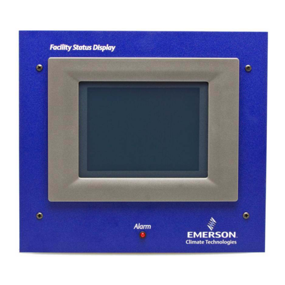
FSD's display module (P/N 750-5100) as
indicated by Step 5 of Figure 2-3.
6. Step 6: Reconnect the 8-pin connector
and RS232 cable to the circuit board in
Step 6 of Figure 2-3.
STEP 5
Back of FSD Panel
Figure 2-3 - Wiring Layout of FSD Enclosure
NOTE: Do not exceed the maximum
Ethernet cable length of 328 feet (100 me-
ters).
2.2. Alarm Relays
• An audible alarm will sound when a new advi-
sory has been received.
• The red alarm LED on the front of the display
module illuminates any time there is an active
advisory.
• The auxiliary relay (dry contact closure) will
activate any time there is an active advisory.
This output allows an external alarm indicator
to be installed away from the board.
2.3. Mounting
The FSD is recess-mounted into a wall or other
Alarm Relays
7. Step 7: Replace the mounting plate back
onto the enclosure and attach using the
four screws.
9.0"
STEP 6
_
+ _
FSD Circuit
Transformer
Board
Inside Back of Enclosure
mounting surface. The face plate with the LCD dis-
play (front portion of the unit) will mount flush
against the surface around the outside of the opening
once the power supply box has been mounted inside
the wall.
1. Cut a rectangular hole into the mounting
surface 8.0" high by 9.0" wide, by at least
3.875" deep (20.32 cm high by 22.86 cm
wide by at least 9.84 cm deep). When
cutting the mounting hole, allow at least
1/2" (1.27 cm) clearance around the hole
for face plate mounting (Figure 2-5).
2. Once this hole is cut, mount the unit as
desired (Figure 2-4), and position the en-
closure so that the four support tabs are
flush against the outside lip of the open-
ing in the wall.
3. Use a screwdriver to bend the four push-
out tabs (two on each side) against the
inside of the drywall so that they hold the
power supply box in place.
_
+
+
8.0"
Installation • 3

