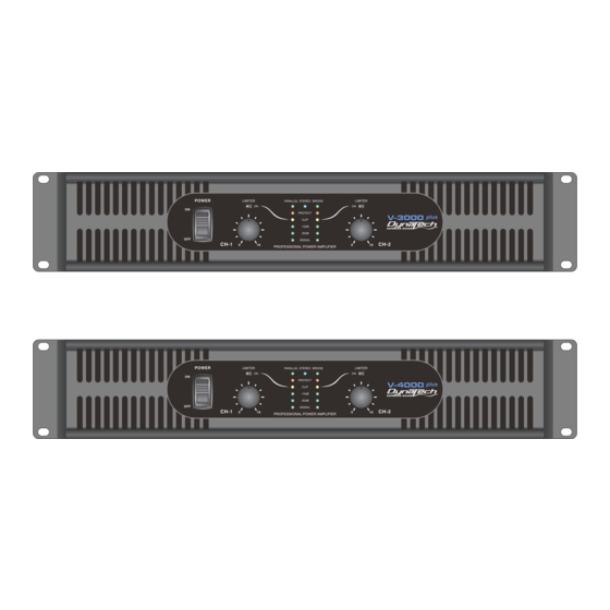
Dynatech V-4000 PLUS 사용자 지침 - 페이지 10
{카테고리_이름} Dynatech V-4000 PLUS에 대한 사용자 지침을 온라인으로 검색하거나 PDF를 다운로드하세요. Dynatech V-4000 PLUS 14 페이지.

P R O F E S S I O N A L
P O W E R
A M P L I F I E R
Front Views & Rear Views | Introduction | Front Panel | Rear Panel | SET UP |
Operating Modes
PARALLEL MONO:
signal, without the need for external jumpers or wiring. Both amplifier channels will operate independently. Though they
carry the same signal, their gain controls affect only their respective channels, and they both must use their respected
speaker outputs. Never attempt to parallel the speaker outputs, this may cause serious damage to your amplifier! This
mode is recommended when using the V PLUS amplifier to run bass speakers, to achieve better low end. To run in
parallel mono mode connect your system as you would if you were going to run in stereo mode. Then flip the mode
switch to Parallel. Be sure the amp is off or the power is disconnected before making any changes.
V-3000 PLUS
Rear Panel
SPEAKERS
2 OHM MINIMUM
SUBWOOFER MODE :
over. The subwoofer operation can be operated in stereo, parallel, or bridge mono modes. Change the different operating
modes by flipping the mode switch on the rear of the unit to your desired operating mode. Also, set the subwoofer mode
switch to the "SUB" position. Use the frequency selector to adjust the subwoofer output frequency from 20Hz to 200Hz.
The different subwoofer modes are listed as follows:
Bridge Subwoofer - This operation allows you to get the most possible power out of your amplifier for the sole purpose
of running a high powered subwoofer loudspeaker in mono. To avoid amplifier overheating, never run the amplifier below
4 ohms in this mode. In this mode you may use the frequency adjustment on the rear of the amp, to control the
frequency output level. Frequencies may be adjusted from 20Hz to 200Hz. Page 9 / Figure 14 details a typical Bridge
Subwoofer set up.
V-3000 PLUS
Rear Panel
V-3000 PLUS / V-4000 PLUS
Parallel ties the two channel line inputs together so that they will both be driven by the same
Either CH-1 or CH-2 input,
or Both inputs.
CH-2 Input
Figure 13 TYPICAL PARALLEL SET-UP
This mode sends low frequencies to your speakers without the use of an external cross-
Do Not Use
CH-2 Input
Figure 14 TYPICAL MONO BRIDGE SET-UP
Operation Mode
CH-1 Input
CH-1
Only Input
Set to
SUB
page 9
| Protection | Specifications
SPEAKERS
2 OHM MINIMUM
SPEAKERS
4 OHM MINIMUM
