Galletti S 52 설치, 사용 및 유지 관리 매뉴얼 - 페이지 4
{카테고리_이름} Galletti S 52에 대한 설치, 사용 및 유지 관리 매뉴얼을 온라인으로 검색하거나 PDF를 다운로드하세요. Galletti S 52 12 페이지. Fan heater for steam operation
DECLARATION OF CONFORMITY
Galletti S.p.A. whose main office is located at 12/a via Romagnoli,
40010 Bentivoglio (BO) - Italy, hereby declares, under its own
responsibility, that the fan heaters belonging to the AREO S series,
indoor units for air-conditioning systems, conform to the specifications
of EEC Directives 73/23, 89/392, 91/368, /93/44, 93/68, 89/336, 83/
97 and subsequent modifications.
G B
Bologna 30/06/2004
Carefully read this handbook
1
BEFORE STARTING INSTALLATION
Carefully read this manual.
Installation and maintenance may be carried out solely by qualified
technicians specifically trained for this type of equipment, in conformity
with current regulations.
On receiving the equipment, check that it has not undergone any damage
during transport.
2
INTENDED USE AND OPERATING LIMITS
Galletti S.p.A. will not accept any liability for damage or injury caused as
a result of:
- installation by non-qualified personnel;
- improper use or use in conditions not allowed by the manufacturer;
- failure to perform the maintenance prescribed in this manual;
- use of spare parts other than original factory parts.
The operating limits are specified at the end of this chapter; usage outside
the stated limits is to be considered improper.
When choosing an installation site, you should observe the following rules:
- The heating unit should not be placed immediately under a socket.
- do not install the unit in places where inflammable gases are present;
- do not expose the unit directly to sprays of water;
- install the unit on walls or ceilings able to withstand its weight; use
accessories suited to the purpose and suitable screw anchors.
Store the unit in its packing container until you are ready to install it to
prevent dust from infiltrating inside it.
Installation, maintenance and cleaning jobs may be carried
out only with the power supply disconnected.
If the unit is installed in a room that is only occasionally used, the
temperature in the room itself must be kept above 0°C or else antifreeze
must be added to the water to prevent it from freezing inside the coil.
Do not attempt to modify the internal wiring or other parts of the unit.
Operating limits
-
thermal carrier fluid
-
max steam pressure: 10 bar
-
max steam temperature: 180°C
-
Air inlet temperature: -10°C to +40°C
-
Power supply: rated voltage +/- 10%
The range comprises 6 models whose features are summarised in the table
of figure 1 where:
RPM number of motor revolutions
Q A
air flow rate
PT
heating capacity (steam pressure 1 bar, 120°C)
Qs
steam consumption
Tbs2 Air outlet temperature
Hmax maximum installation height
LWA sound power level
M
sound pressure level (distance 5m, directional factor 2)
AP66000409 - 01
È severamente vietata la riproduzione anche parziale di questo manuale / All copying, even partial, of this manual is strictly forbidden
Luigi Galletti
President
SAFETY SYMBOLS
ATTENTION
3
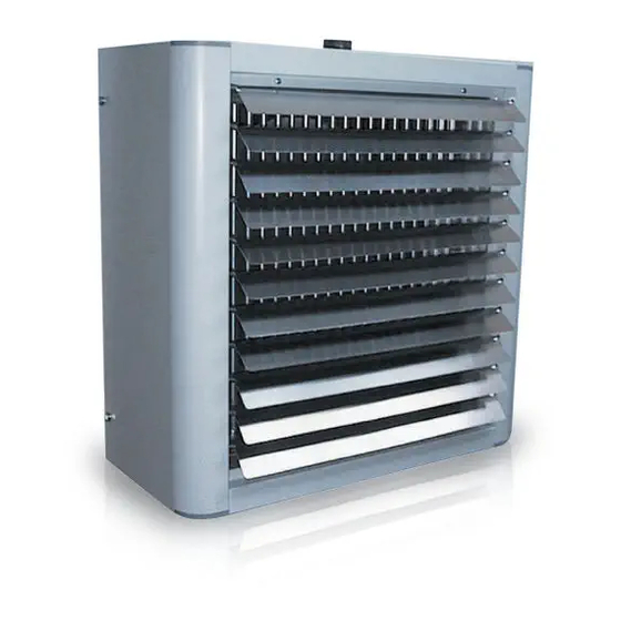
UNIT DESCRIPTION
The fan heater for steam operationare mainly made of the components
listed below.
Prepainted sheet steel cabinet complete with heat-proof ABS corner trim.
The cabinet is complete with adjustable aluminium louvers (spring
operated) placed on the air outlet which allow an optimal distribution of the
air within the heated room. They are supplied with brackets for suspending
the fan heater to the ceiling or joining it to the mounting board for installation
on the wall (accessory).
High conductivity heat exchanger made with copper tubes and aluminium
fins assuring higher heat exchange than standard iron tubes exchangers.
All circuit are in parallel without siphons to drain perfectly the condensed
steam.
All motors are standard equipped with:
- internal thermal protection (klixon)
- windings in class F
- protection degree IP55.
DANGER
- Two speeds, 4/6 poles or 6/8 poles, in the 400 / 3 / 50 version, delta-
VOLTAGE
star type.
Axial fan with statically balanced sickle blades housed in a specially
designed compartment that enhances ventilation and reduces noise
emissions.
Safety grille made of electrogalvanised steel wire: it supports the motor
and is fixed to the cabinet by means of vibration damping supports.
Main components as shown in figure 2:
(1)
Cabinet: side panel
(2)
Cabinet: upper panel
(3)
Cabinet: lower panel
(4)
Rear panel/fan compartment
(5)
Safety grille (fan) supporting motor
(6)
Finned block heat exchanger (heat exchanger coil)
(7)
Adjustable louvers
(8)
Conveyor duct
(9)
Plastic corner trim on cabinet (left and right)
(10)
Wall/ceiling mounting brackets
4
DIMENSIONS
Figure 3 shows the dimensions of the unit:
IN
Steam inlet connection, 1"
OUT Condensate drain connection, 1"
5
INSTALLATION
Remove the fan heater from the packing container and check that no
damage has occurred during transport.
Before starting to install the unit, make sure that the installation height and
air range conform to the specifications provided in the technical catalogue,
according to the number of motor poles and type of air flow (vertical or
horizontal). The maximum installation height is also shown in figure 4.
In the case of wall installation, use suitable mounting boards, available as
accessories:
DFP for wall mounting
DFC for mounting on columns
Adjustable DFO for mounting on walls/columns (from 0° to ±45°).
If you do not use the mounting boards supplied by the manufacturer, make
sure in any case that the unit is adequately spaced from the wall or ceiling,
at a distance that is at least that shown in figure 5.
Use screw anchors of adequate dimensions to support the weight of the
unit and make sure that the surface of the installation site is suited to the
purpose.
Using suitable lifting equipment (a forklift truck is recommended), convey
the unit to the installation site and rest it on the floor with the fins facing down.
The feeding hose should be connected to the upper coupling and the
condensate drainage hose to the lower coupling. Fig. 6 shows an example
of water connection diagram where the condensate drainage hose, at the unit
outlet, is provided with a drainage trap, a Y filter, a condensate drainage,
a flow indicator and a regulating valve.
4
/
female gas
1
4
1
/
female gas
4