Maico 0157.0344 조립 및 작동 지침 - 페이지 4
{카테고리_이름} Maico 0157.0344에 대한 조립 및 작동 지침을 온라인으로 검색하거나 PDF를 다운로드하세요. Maico 0157.0344 8 페이지. Radio switch
Instructions in respect of radio operation
•
The XS 1 radio switch may be used in all
European Union countries.
•
The combination of this radio equipment with
other communication networks is only
permitted within the framework as laid down
by national statutes.
•
This radio equipment may not be used for
communication that goes beyond property
boundaries.
•
When used within Germany, you must take
note of and abide by the instructions given in
the relevant section of the Official Journal „Vfg
73/200".
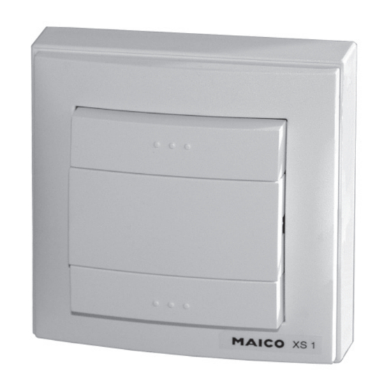
Overview
1 Surface-mounted housing 3 Protective cover
2 Transmitter
4 Switch insert
2.1 Battery compartment,
4.1 Switch ON, up
2 batteries (CR 2032, 3V) 4.2 Switch OFF, down
2.2 DIP switch
2.3 Antenna
Radio transmission
Radio transmission is carried out over a non-
exclusive transmission path. The possibility of
interference cannot be ruled out.
Radio transmission is not suitable for the
switching of safety equipment, such as
emergency cut-out switches or emergency
alarm call equipment.
In a clear area, the transmission range of the
radio switch is a maximum of 100 metres. This
is however, dependant on the construction
environment of the object in question and as a
rule, is less than this:
Dry material
Wood, plaster, plasterboard
Bricks, chipboard
Reinforced concrete
Metal, metal grille,
aluminium lamination
Installation
The radio switch is installed in a surface-mounted
housing [1] or in a recessed-mounted box, to be
supplied by the customer.
1. Secure the surface-mounted housing [1] to
the wall with appropriate material. If required,
holes can be drilled in the housing or
alternatively, it can be fixed to a plate with the
adhesive provided.
2. Fix the transmitter [2] into a surface- or re-
cessed-mounted housing with 2 screws. Make
sure the side marked „TOP" is uppermost.
3. Insert the antenna [2.3] into the surface-
mounted housing above the plate. Concealed
mounting: In order to achieve maximum
reception performance, install the antenna if
possible remote from the receiver, fully
extended and away from any large metal
surfaces, such as door frames, etc. Under
no circumstances should the antenna be
bent, uninsulated, shortened or leng-
thened.
4. Move switch 1 „Batt" on the DIP switch [2.2]
to ON.
5. Check the DIP switch positions. All 4 DIP
switches should be set to the right.
6. Position the switch insert [4] into the protective
Penetration
cover [3] and plug the whole unit carefully
approx. 90%
onto the receiver [2], until the springs click
approx. 70%
into place. Make sure that the 10 pin plug
approx. 30%
socket and the two springs are not damaged.
approx. 10%
Setting up the radio receiver
The radio receiver must be installed and the
fan must be connected. Please refer also to
the radio receiver instructions.
The radio receiver is tuned to the transmission
channel (transmission frequency) of the trans-
mitter by „learning" a radio telegram from the
transmitter.
An unlimited number of radio receivers can be
assigned to one transmission channel. The
assignment is made in each corresponding
receiver.