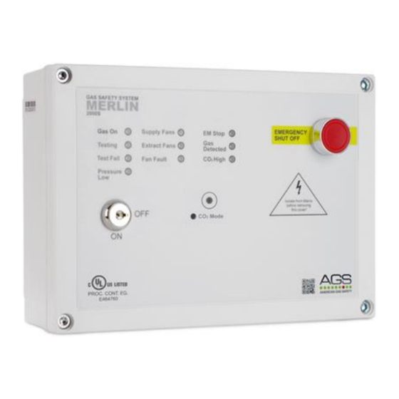
AGS Merlin 2000S 설치 및 운영 매뉴얼 - 페이지 4
{카테고리_이름} AGS Merlin 2000S에 대한 설치 및 운영 매뉴얼을 온라인으로 검색하거나 PDF를 다운로드하세요. AGS Merlin 2000S 12 페이지. Gas proving and ventilation interlock system
AGS Merlin 2000S에 대해서도 마찬가지입니다: 사용자 설명서 (12 페이지), 설치 및 운영 매뉴얼 (12 페이지)

Installation & Operation Manual
Installation
Planning
This panel is designed for use when the kitchen appliances do not have flame failure devices fitted,
therefore gas proving is a requirement.
The Merlin 2000S system acts as an interlock between the ventilation system and the gas solenoid
valve. The system is compatible with both current monitors and air pressure differential switches in
order to interlock with up to 4 fans.
The fans can be monitored through air pressure switches or by means of an additional current monitor.
To operate the Merlin 2000S the fans should be turned to the 'on' position, once the panel receives a
signal to indicate the fans are operating the key on the panel can be turned to the 'on' position and this
will open the gas solenoid valve. If the fans should fail, the 'fan fail' LED on the panel will illuminate and
the gas solenoid will close.
The Merlin 2000S can work in conjunction with carbon dioxide, natural gas, carbon monoxide and
LPG sensors.
Please refer to your detector manual for important information regarding coverage, location and
positioning including areas and conditions to avoid.
Fixing - Mounting
Place the panel 48-60 inches above finished floor level.
Unpack all the parts!
Designed for surface mounting, it must be installed by a
licensed, insured contractor.
1. Carefully remove the front cover from the unit by
unscrewing the four bolts located at each corner.
To do this – use the socket wrench provided.
2. Mark the four screw holes located on the back of the enclosure to the wall. Ensure the wall surface is
flat to prevent base distortion.
3. After executing the mounting and the connections – replace the front cover and insert the security
caps over the four bolts.
Take care when making connections to high voltage connectors!
Any damage attempting to remove the circuit board may void any warranty!
All Class 2 wiring is to be installed within flexible tubing to maintain segregation between circuits!
Wiring of different circuits shall be separated by means of routing, clamping or barrier!
A flush mount kit is available, comprising of a mounting bracket and decorative surround strip. Contact
your supplier for more information.
Rev: 10
02-21
Merlin 2000S
4
