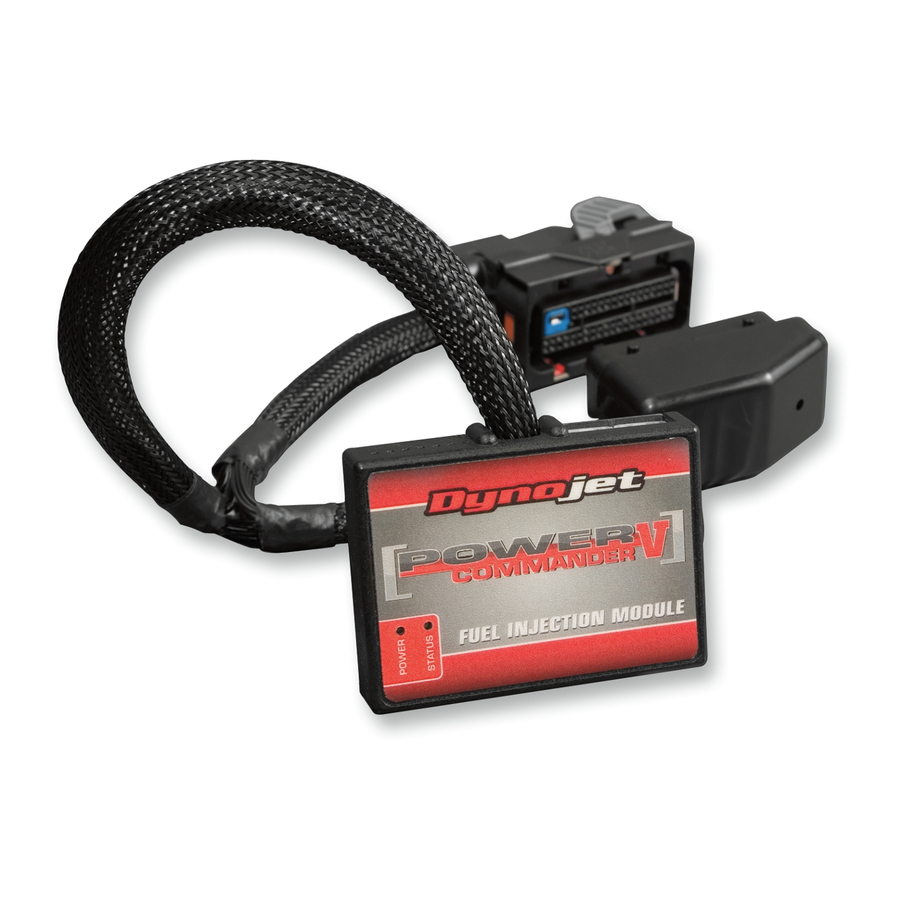
Dynojet Power commander V 설치 지침 - 페이지 5
{카테고리_이름} Dynojet Power commander V에 대한 설치 지침을 온라인으로 검색하거나 PDF를 다운로드하세요. Dynojet Power commander V 5 페이지. 2017-2018 polaris scrambler 1000, 2017-2018 polaris sportsman 1000
Dynojet Power commander V에 대해서도 마찬가지입니다: 설치 지침 매뉴얼 (6 페이지), 설치 지침 매뉴얼 (9 페이지), 설치 지침 매뉴얼 (7 페이지), 설치 지침 (4 페이지), 설치 지침 (5 페이지), 설치 지침 (4 페이지), 설치 지침 (5 페이지), 설치 지침 (4 페이지), 설치 지침 (5 페이지), 설치 지침 매뉴얼 (6 페이지), 설치 지침 매뉴얼 (6 페이지), 설치 지침 (5 페이지), 설치 지침 매뉴얼 (6 페이지), 설치 지침 (5 페이지), 설치 지침 매뉴얼 (6 페이지), 설치 지침 (5 페이지), 설치 지침 (5 페이지), 설치 지침 매뉴얼 (7 페이지), 설치 지침 (5 페이지), 설치 지침 (4 페이지), 설치 지침 매뉴얼 (6 페이지), 설치 지침 (4 페이지), 설치 지침 (5 페이지), 설치 지침 매뉴얼 (6 페이지), 설치 지침 매뉴얼 (8 페이지), 설치 지침 (4 페이지), 설치 지침 매뉴얼 (7 페이지), 설치 지침 매뉴얼 (6 페이지), 설치 지침 매뉴얼 (8 페이지), 설치 지침 (4 페이지), 설치 지침 매뉴얼 (6 페이지), 설치 지침 (4 페이지), 설치 지침 (4 페이지), 설치 지침 매뉴얼 (6 페이지), 설치 지침 (5 페이지), 설치 지침 (5 페이지), 설치 지침 매뉴얼 (6 페이지), 설치 지침 매뉴얼 (6 페이지), 설치 지침 매뉴얼 (6 페이지), 설치 지침 매뉴얼 (7 페이지), 설치 지침 매뉴얼 (6 페이지), 설치 지침 (5 페이지), 설치 매뉴얼 (5 페이지), 설치 지침 매뉴얼 (6 페이지), 설치 지침 및 사용 설명서 (8 페이지), 설치 지침 및 사용 설명서 (6 페이지), 설치 매뉴얼 (4 페이지), 설치 매뉴얼 (7 페이지), 설치 매뉴얼 (6 페이지), 설치 지침 매뉴얼 (6 페이지), 설치 지침 매뉴얼 (6 페이지), 설치 지침 (5 페이지), 설치 지침 (5 페이지), 설치 지침 매뉴얼 (6 페이지), 설치 지침 매뉴얼 (8 페이지), 설치 매뉴얼 (5 페이지), 설치 매뉴얼 (9 페이지), 설치 매뉴얼 (4 페이지), 설치 지침 (4 페이지), 설치 지침 매뉴얼 (6 페이지), 설치 지침 매뉴얼 (7 페이지), 설치 지침 매뉴얼 (7 페이지), 설치 지침 (5 페이지), 설치 지침 (7 페이지), 설치 지침 (4 페이지), 설치 지침 (4 페이지), 설치 지침 (5 페이지), 설치 지침 (5 페이지), 설치 지침 매뉴얼 (6 페이지), 설치 지침 (5 페이지), 설치 지침 매뉴얼 (5 페이지), 설치 지침 매뉴얼 (6 페이지), 설치 지침 매뉴얼 (7 페이지), 설치 지침 (4 페이지), 설치 지침 매뉴얼 (7 페이지), 설치 지침 (5 페이지), 설치 지침 (4 페이지), 설치 지침 (4 페이지), 설치 지침 (4 페이지), 설치 지침 (5 페이지), 설치 지침 (5 페이지), 설치 지침 (4 페이지), 설치 지침 (5 페이지), 설치 지침 (4 페이지), 설치 지침 (4 페이지), 설치 매뉴얼 (6 페이지), 설치 지침 (4 페이지), 설치 지침 (5 페이지), 설치 지침 매뉴얼 (7 페이지), 설치 지침 (4 페이지), 설치 지침 (5 페이지), 설치 지침 (5 페이지), 설치 매뉴얼 (6 페이지), 설치 지침 (4 페이지), 설치 지침 매뉴얼 (7 페이지), 설치 지침 매뉴얼 (6 페이지), 설치 지침 (4 페이지), 설치 지침 매뉴얼 (6 페이지)

