Dynojet Power commander V 설치 지침 매뉴얼 - 페이지 5

{카테고리_이름} Dynojet Power commander V에 대한 설치 지침 매뉴얼을 온라인으로 검색하거나 PDF를 다운로드하세요. Dynojet Power commander V 6 페이지. 2017-2018 polaris scrambler 1000, 2017-2018 polaris sportsman 1000
Dynojet Power commander V에 대해서도 마찬가지입니다: 설치 지침 매뉴얼 (6 페이지), 설치 지침 매뉴얼 (9 페이지), 설치 지침 매뉴얼 (7 페이지), 설치 지침 (4 페이지), 설치 지침 (5 페이지), 설치 지침 (4 페이지), 설치 지침 (5 페이지), 설치 지침 (4 페이지), 설치 지침 (5 페이지), 설치 지침 매뉴얼 (6 페이지), 설치 지침 매뉴얼 (6 페이지), 설치 지침 (5 페이지), 설치 지침 매뉴얼 (6 페이지), 설치 지침 (5 페이지), 설치 지침 매뉴얼 (6 페이지), 설치 지침 (5 페이지), 설치 지침 (5 페이지), 설치 지침 매뉴얼 (7 페이지), 설치 지침 (5 페이지), 설치 지침 (4 페이지), 설치 지침 매뉴얼 (6 페이지), 설치 지침 (4 페이지), 설치 지침 (5 페이지), 설치 지침 매뉴얼 (6 페이지), 설치 지침 매뉴얼 (8 페이지), 설치 지침 (4 페이지), 설치 지침 매뉴얼 (7 페이지), 설치 지침 매뉴얼 (6 페이지), 설치 지침 매뉴얼 (8 페이지), 설치 지침 (4 페이지), 설치 지침 매뉴얼 (6 페이지), 설치 지침 (4 페이지), 설치 지침 (4 페이지), 설치 지침 매뉴얼 (6 페이지), 설치 지침 (5 페이지), 설치 지침 (5 페이지), 설치 지침 매뉴얼 (6 페이지), 설치 지침 매뉴얼 (6 페이지), 설치 지침 매뉴얼 (6 페이지), 설치 지침 매뉴얼 (7 페이지), 설치 지침 매뉴얼 (6 페이지), 설치 지침 (5 페이지), 설치 매뉴얼 (5 페이지), 설치 지침 매뉴얼 (6 페이지), 설치 지침 및 사용 설명서 (8 페이지), 설치 지침 및 사용 설명서 (6 페이지), 설치 매뉴얼 (4 페이지), 설치 매뉴얼 (7 페이지), 설치 매뉴얼 (6 페이지), 설치 지침 매뉴얼 (6 페이지), 설치 지침 (5 페이지), 설치 지침 (5 페이지), 설치 지침 매뉴얼 (6 페이지), 설치 지침 매뉴얼 (8 페이지), 설치 매뉴얼 (5 페이지), 설치 매뉴얼 (9 페이지), 설치 매뉴얼 (4 페이지), 설치 지침 (4 페이지), 설치 지침 매뉴얼 (6 페이지), 설치 지침 매뉴얼 (7 페이지), 설치 지침 매뉴얼 (7 페이지), 설치 지침 (5 페이지), 설치 지침 (7 페이지), 설치 지침 (4 페이지), 설치 지침 (4 페이지), 설치 지침 (5 페이지), 설치 지침 (5 페이지), 설치 지침 매뉴얼 (6 페이지), 설치 지침 (5 페이지), 설치 지침 매뉴얼 (5 페이지), 설치 지침 매뉴얼 (6 페이지), 설치 지침 매뉴얼 (7 페이지), 설치 지침 (4 페이지), 설치 지침 매뉴얼 (7 페이지), 설치 지침 (5 페이지), 설치 지침 (4 페이지), 설치 지침 (4 페이지), 설치 지침 (4 페이지), 설치 지침 (5 페이지), 설치 지침 (5 페이지), 설치 지침 (5 페이지), 설치 지침 (4 페이지), 설치 지침 (5 페이지), 설치 지침 (4 페이지), 설치 지침 (4 페이지), 설치 매뉴얼 (6 페이지), 설치 지침 (4 페이지), 설치 지침 (5 페이지), 설치 지침 매뉴얼 (7 페이지), 설치 지침 (4 페이지), 설치 지침 (5 페이지), 설치 지침 (5 페이지), 설치 매뉴얼 (6 페이지), 설치 지침 (4 페이지), 설치 지침 매뉴얼 (7 페이지), 설치 지침 매뉴얼 (6 페이지), 설치 지침 (4 페이지), 설치 지침 매뉴얼 (6 페이지)
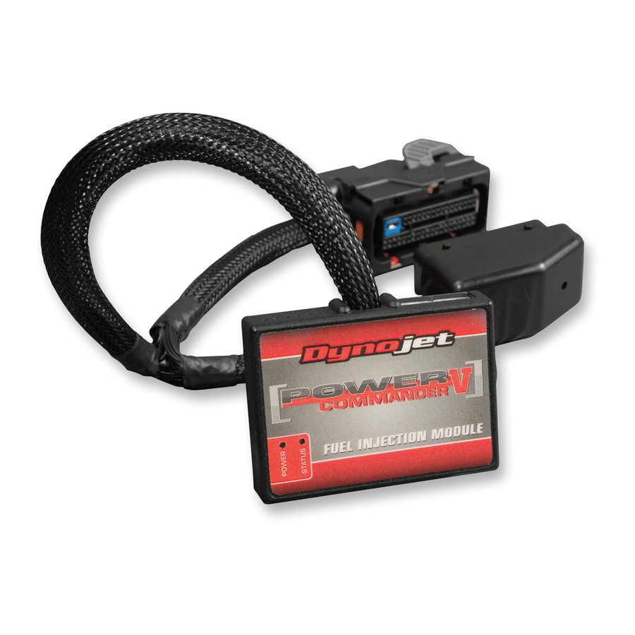
Dynojet Power commander V 설치 지침 매뉴얼
FIG.G
FIG.H
Front O2 cable
FIG.J
I15-012
www.powercommander.com
9
Plug the supplied WHITE O2 Optimizer into the bike's wiring harness
in-place of the stock O2 sensor (Fig. G).
There is a BLACK O2 Optimizer (rear) and a WHITE O2 Optimizer (front)
in the kit. They are indexed so they can NOT be connected incorrectly.
The stock O2 sensor will no longer be used. It can be removed from
the exhaust if desired and if you have a way to plug the hole left in the
exhaust.
10 Reinstall the side covers and the seat (unless you are also installing the
Auto-tune accessory).
IF INSTALLING THE AUTO-TUNE KIT (PN: AT-101B) FOLLOW THESE STEPS:
11 Install the Auto-tune wideband O2 sensors into the exhaust pipes (for a more
detailed explanation, see the Auto-tune install guide).
The stock O2 sensor bung size is not the same that the Auto-tune wideband O2
sensors require (18mm x 1.5). You will likely need to weld the supplied bungs to
the exhaust to use Auto-tune.
12 Connect the O2 sensor cables to the wideband O2 sensors in the exhaust and
route the cables towards the PCV under the seat (Fig. H).
Use the longer (52") cable for the front cylinder O2 sensor and the shorter cable
(24") for the rear cylinder O2 sensor. Route the front cylinder cable down and to
the rear of the bike following alongside the stock wiring harness that is along the
lower right frame rail. Then come back upwards along with the stock harness to
beneath the right side cover and then under the seat and towards the PCV.
13 Relocate the stock 6-pin diagnostic connector to the location shown in
Figure J.
The original location can be seen in Figure H.
14 From under the seat, route the 6-pin 12v power supply connector from the
Auto-tune module under the frame rail to the right hand side of the bike and
connect the 6-pin connector from the Auto-tune module to the stock 6-pin
diagnostic connector (Fig. J).
2015 Harley Davidson Street 500 - PCV - 5