JADO 42486.100 설치 지침 - 페이지 2
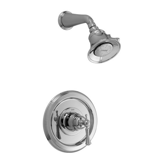
{카테고리_이름} JADO 42486.100에 대한 설치 지침을 온라인으로 검색하거나 PDF를 다운로드하세요. JADO 42486.100 2 페이지. Pressure balanced shower trim kit
TOOLS REQUIRED
Channel Locks
Tubing Cutter
Adjustable Wrench
ROUGHING-IN DIMENSIONS
For reference
FINISHED WALL
1-5/8" TO 3-1/4"
2" REF.
1/2" NPT
OPTIONAL TO
2-1/2"
FINISHED FLOOR
USUALLY
BETWEEN
9-3/8"
72'' AND 84"
NOTE: ALL DIMENSIONS
ARE TYPICAL TO B/S
WITH DIVERTER
SHW
7-7/8" D.
TUB
48" TO 54"
OPTIONAL
BOTTOM OF
TUB
OR SHOWER
STALL
5
6
8
9
11
12
10
Phillips Screwdriver
Plumbers' Putty or Caulking
Regular Screwdriver
Teflon Tape
INSTALL TRIM
1
CAUTION: Protect finish on SHOWER ARM
and SHOWER HEAD when installing.
Push CAP (1) onto VALVE CARTRIDGE (2). Mount
ESCUTCHEON (3) with gasket to valve body and secure
with SCREWS (4).
Push the COVER (5) as shown over the CAP (1) and align
prongs on COVER (5) with screw holes in ESCUTCHEON (3).
Important! Make sure COVER (5) snaps over the SCREWS (4).
Push ADAPTER (6) onto CARTRIDGE STEM (7). Push
ESCUTCHEON (8) onto ADAPTER (6). Mount CROSS
HANDLE (9) or LEVER HANDLE (10) and secure with
WASHER and SCREW (11). Cover with CAP (12).
Remove pipe cap from pipe. Apply sealant or Teflon tape
to threads of shower connections. Install SHOWER ARM (13)
to shower elbow. Thread SHOWER HEAD (14) onto SHOWER
ARM (13).
APPLY
SEALANT
13
APPLY
SEALANT
14
1
3
2
7
4
2
ADJUST HOT LIMIT STOP
By restricting HANDLE rotation and limiting the amount of hot water allowed to mix with the cold, the HOT LIMIT
SAFETY STOP (1) reduces risk of accidental scalding. To set the maximum hot water temperature of your faucet, all
you need to do is adjust the setting on the HOT LIMIT SAFETY STOP (1).
Turn CARTRIDGE STEM (2) to the OFF position (coldest setting) before making adjustment to HOT LIMIT STOP (1). Use
a flat blade screwdriver to pry free the HOT LIMIT SAFETY STOP (1). Pull forward and rotate counterclockwise one number
to limit hot water temperature. Use ARROW (3) on CARTRIDGE (4) and NUMBERS (5) on HOT LIMIT STOP (1) for indication.
2
3
TEST INSTALLED FITTING
PIPE
CAP
Turn VALVE "off".
With HANDLE (1) in "off" position, turn on water supplies and check all
connections for leaks.
Operate HANDLE (1) and flush water lines thoroughly. Check the function for
proper operation.
4
BACK TO BACK INSTALLATION
(SEE ILLUSTRATION STEP 5 FOR REFERENCE)
Remove Handle and Trim from Valve. See step 1 for reference.
Remove PRESSURE BALANCE UNIT (5). Rotate PRESSURE BALANCE UNIT (5) 180˚ so that the inlets face up and the
large outlet port faces down.
Push PRESSURE BALANCE UNIT (5) in casting make sure inlets line up with holes in bottom of casting. Top
flange should butt up against top of casting.
Reassemble FIXATION RING (4) and CARTRIDGE (1).
1 0 9 6 7 3
3
3
2
5
HOTTER
(Smaller Numbers)
0 1 3 5 7 9 11 13 15
1
5
4
4
COLDER
1
(Larger Numbers)
0 1 3 5 7 9 11 13 15
1
1 0 9 6 7 3