Jafar 4497 운영 매뉴얼 - 페이지 9
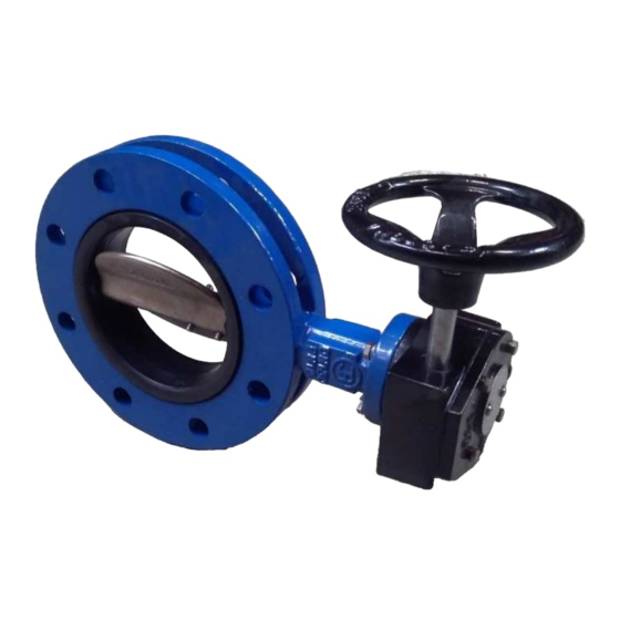
{카테고리_이름} Jafar 4497에 대한 운영 매뉴얼을 온라인으로 검색하거나 PDF를 다운로드하세요. Jafar 4497 11 페이지. Concentric butterfly valves
Before attempting to install the valve, remove the main bore plugs, check the inner surfaces of the valve and
thoroughly flush with water, if necessary. Before installing the valve between the pipeline flanges, first remove all
shipping preservation from the surfaces, thoroughly clean the flange faces, install the properly selected seals (this
step applies to P/N 4496 only) and tighten the piping and valve flanges together with sufficiently long and properly
sized bolts or threaded bars. The valve and piping flange holes must be aligned. Tighten the connection flange
bolts crosswise to ensure a proper seal pressure. Start from the bolt holes near the valve pivot shaft. The tightening
torque of the bolt nuts is specified in the PN-63/M-82056. Install the valve on a base or a support sufficient for the
size and weight of the valve, to prevent straining of the piping by the valve. The valve must feature a suitable
operator, i.e. a handwheel and a gearbox, a gearbox in a rigid housing, an electric drive unit, or an operating drive
gearbox on a pedestal. When installing a housing, it is necessary to use a street box founded on a base slab. When
using a spindle extension, make sure that
the weight of the extension is not transferred to the valve spindle. To prevent the load transfer, use holding pieces,
mounted to the chamber/vault walls.
Having completed the installation, perform a pressure test at a maximum test pressure equal to 1.5 times the
nominal pressure in the fully open or 1.1 times the nominal pressure in fully closed position.
Caution! If the product has mechanical damage, do not install it in the pipeline.
Due to the non-uniformity of the speed and pressure fields near piping elbows and tees, it is recommended to
maintain a straight piping run at least 5 × DN long between the valve outer flange face and the piping bend or tee.
Fig. 5.
Recommended distances from the piping bends
For the valves in the size range of DN200 to DN2000, the axis of the closure drive shaft must be perpendicular
to the centreline of the piping bend (an elbow or a tee) (see Fig. 5).
The general rule is not to install the valve near any bend or tee or any piping bends (elbows / tees), especially with
the valve on the high-pressure side of the piping (in the pump to valve to piping curve system) (see Fig. 5). The
normal flow deflection over a piping bend will be aggravated by the low-pressure area of the valve (where a risk
of flow interruption exists).
Irrespective of the requirement for a straight piping run at least 5 × DN long between the valve outer flange face
and the piping bend (alternatively, the designed valve can be replaced with one of a higher pressure rating), to
minimise the localised flow acceleration and interruption by the piping bend. The valve shall be installed with the
centreline of the valve closure pivot shaft perpendicular to the vertical line of the piping bend so that the valve
closure drive shaft centreline is aligned with the piping bend plane. Apart from normal flow deflection by the
piping bend, the liquid flow applies a high strain in the low-pressure valve area. This generates a very high
hydrodynamic moment.
The pipe inner diameter shall be equal to the nominal diameter (DN) of the valve plus the tolerance for the
deviations provided for by the foundry industry for the given pipe I.D.
If the valve is installed with an operator or an operator and gearbox unit, check the electrical wiring and fire-proof
protection features (also during coupling and adjustment of the operator) for conformity with the respective
operating manuals from the operator drive unit manufacturer.
Caution! If the product has mechanical damage, do not install it in the pipeline.
Caution! When mounting the butterflay valve with the electric actuator in the horizontal position, it is
absolutely necessary to use a support or slings in order to relieve the valve, see example below.
OPERATING MANUAL
07-2021
9/11