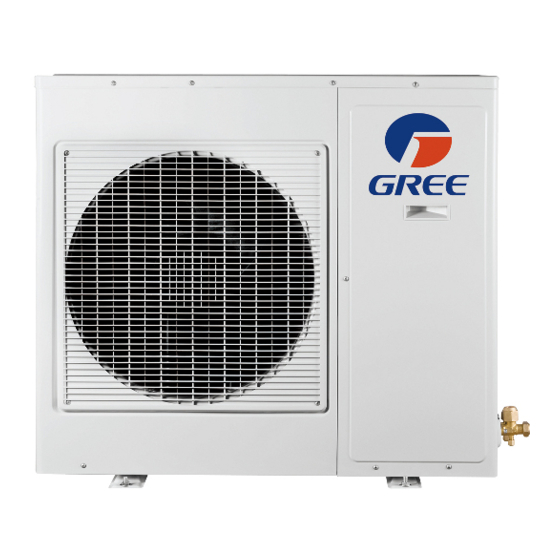
Gree GWHD(30)ND3CO 소유자 매뉴얼 - 페이지 7
{카테고리_이름} Gree GWHD(30)ND3CO에 대한 소유자 매뉴얼을 온라인으로 검색하거나 PDF를 다운로드하세요. Gree GWHD(30)ND3CO 11 페이지. Multi
ductless inverter
Gree GWHD(30)ND3CO에 대해서도 마찬가지입니다: 설치 매뉴얼 (16 페이지)

- 1. Table of Contents
- 2. Conformity and Range
- 3. The Instructions before Use
- 4. Name of Parts
- 5. Technical Data
- 6. Outdoor Unit Working Temperature Range
- 7. Electrical Connections
- 8. Installing the Outdoor Unit
- 9. Bleeding
- 10. Maintenance
- 11. Installation Dimension Diagram
- 12. Check after Installation
ELECTRICAL CONNECTIONS
GWHD(24)ND3CO
1. Remove the handle at the right side plate of the
outdoor unit (ten screw).
.
Remove the cable clamp, connect the connection cable
2
and power cable with the terminal at the row of connection
and fix the connection. The fitting line distributing must be
consistent with the indoor unit terminal of line bank.
Wiring should meet that of indoor unit.
Fix power connection wire by wire clamp.
3.
4.
Ensure wire has been fixed well.
Install the handle.
5.
An all-pole disconnection switch having a contact
separation of at least 3mm in all pole should be
connected in fixed wiring.
Wrong wire connection may cause malfunction of some
electric components.After fixing cable, ensure that
leads between connection to fixed point have some space.
The connection pipes and the connectiong wirings of
the unit A ,unit B and unit C must be corresponding to each
other respective.
The appliance shall be installed in accordance with
national wiring regulations.
Do not install the outdoor unit where it is exposed
to the sunlight.
Note: the above figures are only intended to be a simple
i d
g a
a r
m
f o
h t
a e
p
i l p
n a
e c
appearance of the units that have been purchased.
a
d n
m
y a
n
t o
o c
r r
s e
o p
d n
To unit A
L1 L2
power
cable
To the power supply
L1
L2
Indoor unit
connection cable
connection cable
o t
t
e h
1)
The power cable should be put in from the hole under
connection cable cover.
2)
If connecting with two indoor units, the connection cable
should be put in from hole A and hole B.
3)
If connecting with three indoor units, the connection cable
should be put in from hole A , B and C.
4)
If connecting with four indoor units, the connection cable
should be put in from hole A, B , C and D.
All power cables and connection cables must be protected with conduits.
6
INS TALLER
To unit B
connection
connection
cable
cable
L1
L2
D
connection cable
C
B
connection cable
A
Power cable
To unit C
connection
cable
Outdoor unit
