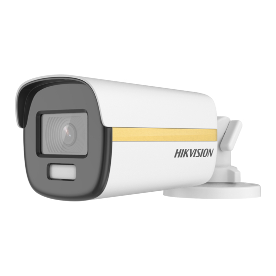
HIKVISION ColorVu DS-2CE10KF3T-E 사용자 설명서 - 페이지 8
{카테고리_이름} HIKVISION ColorVu DS-2CE10KF3T-E에 대한 사용자 설명서을 온라인으로 검색하거나 PDF를 다운로드하세요. HIKVISION ColorVu DS-2CE10KF3T-E 19 페이지. Bullet & turret camera

Loosen the trim ring to adjust the pan position
1).
[0° to 360°].
Loosen the thumbscrew to adjust the tilt
2).
position [0° to 180°].
Loosen the screw to adjust the rotation position
3).
[0° to 360°].
7. Tighten the trim ring and screws to finish the
installation.
2.1.2 Ceiling/Wall Mounting of Type II camera Without
Junction Box
Before you start:
Ceiling mounting and wall mounting are similar.
Following steps take ceiling mounting as an example.
Steps:
1. Paste the drill template (supplied) to the place
where you want to install the camera.
2. (Optional) For cement ceiling, drill the screw holes
with a 5.5 mm drill and insert the supplied wall
plugs.
3. (Optional) Drill the cable hole, when the cables are
routed through the ceiling.
4. Route and connect the power cord and video cable.
5. Align the screw holes in the bracket to the ceiling,
and secure the camera with three PA4 × 25 screws
(supplied).
Figure 2-5 Secure Camera to Ceiling
6. Power on the camera to check whether the image
on the monitor is gotten from the optimum angle. If
not, turn the trim ring counterclockwise to loosen it
and adjust the positions according to the figure
below.
Rotation Position
[0° to 360°]
7. Turn the trim ring clockwise to lock the positions.
2.1.3 Ceiling/Wall Mounting with Junction Box
Before you start:
Figure 2-3 3-Axis Adjustment
Figure 2-4 Drill Template
Figure 2-6 3-Axis Adjustment
Screw Hole
Screw Hole
Screw Hole
templat e
3
Pan Position
[0° to 360°]
Trim Ring
Tilt Position
[0° to 90°]
