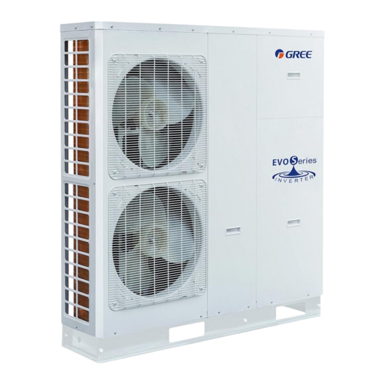
Gree HLR12Pd/Na-M 유닛 설치 매뉴얼 - 페이지 7
{카테고리_이름} Gree HLR12Pd/Na-M에 대한 유닛 설치 매뉴얼을 온라인으로 검색하거나 PDF를 다운로드하세요. Gree HLR12Pd/Na-M 18 페이지. Mini chiller

1L1
3L2
5L3
13
21
NC
A1
NO
14
22
A2
NO
NC
2T1
4T26
T3
AC Contactor 1
1L1
3L2
5L3
13
21
NC
A1
NO
14
22
A2
NO
NC
2T1
4T26
T3
AC Contactor 2
(2) See the following statement for installation of two groups of auxiliary electric heaters, including wiring of
the AC contactors and the tank-type electric heater.
Wiring of the AC contactors is the same as that stated above.
◆
When the thermostat is not required, do the wiring as shown in the diagram below. The output terminal
◆
used to control the thermostat should be short-circuited and then be connected to terminal 9 ( it is the
terminal for the neutral line).
Field Installation Diagramof the Electric Heater
(with the thermostat)
6
7
8
Wiring Board
34
35
36
Thermostat
Neutral Line
5
Electric Box
6
X17
7
X18
8
Main Board AP1
34
35
CN26
CN27
36
XT2
Tank-type Electric Heater
Sensing probe
Unit Installation
