Gree GMV BACnet 기술 및 서비스 매뉴얼 - 페이지 13
{카테고리_이름} Gree GMV BACnet에 대한 기술 및 서비스 매뉴얼을 온라인으로 검색하거나 PDF를 다운로드하세요. Gree GMV BACnet 20 페이지.
Notice!
Main control ODU or gateway at the top/end of CAN bus must be with matched resistance;
otherwise the communication might be wrong!
※CAN bus: specific meaning shall refer to the specification Internet topological graph.※
The No.8 dial-up button in function dial-up machine shall be used in the setting in the matched
resistance of CAN bus in this gateway.
When the gateway is at the top/end of CAN bus, the gateway shall be with the matched
resistance, then dial the No.8 function dial-up machine to 0;
When the gateway is not at the top/end of CAN bus, the gateway is not with the matched
resistance, then dial it to 1.
set to be with the
matched resistance
main control unit
of ODU system 1
set to be with the
matched resistance
n stands for the quantity of ODU system, n≤16.
Dial-up setting graph for the matched resistance:
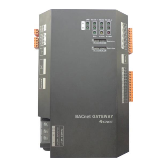
1.2 LED DISPLAY
The above LED indicator is mainly consisting of two parts: status indicator (run, alarm, power)
and communication indicator (CAN, RS485, RS2332). The following table is the working status of
each indicator.
GMV BACnet Gateway Technical Service Manual
CAN bus
main control unit of
main control unit of
ODU system 1
ODU system 2
set not to be with the
matched resistance
CAN bus
main control unit
of ODU system 2
set not to be with
set not to be with the
matched resistance
......
set not to be with the
matched resistance
......
the matched
resistance
10
main control unit of
ODU system n
set to be with the
matched resistance
main control unit
of ODU system n
set to be with the
matched resistance