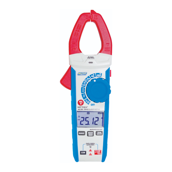
Major tech MT723 사용 설명서 - 페이지 11
{카테고리_이름} Major tech MT723에 대한 사용 설명서을 온라인으로 검색하거나 PDF를 다운로드하세요. Major tech MT723 16 페이지. Ac/dc trms clamp meter

7.2. AC Voltage Measurement
1.lnsert the black test lead into the negative COM terminal and the red
test lead into the positive V
2. Set the function switch to the V~ position.
3. Press the MODE/VFD key for 1 second to turn on the VFD test.
4. Press the PEAK key to tum on Peak test.
5. Connect the test leads in parallel to the circuit under test.
6. Read the voltage measurement on the LCD display.
7.3. DC Voltage Measurement
1. lnsert the black test lead into the negative COM terminal and the red
test lead into the positive V
2. Set the function switch to the V~ position.
3. Connect the test leads in parallel to the circuit under test.
4. Read the voltage measurement on the LCD display.
7.4. Capacitance Measurements
WARNING: To avoid electric shock, discharge the capacitor under
test before measuring.
1. Set the function switch to the CAP position.
2. lnsert the black test lead banana plug into the negative COM jack and
the red test lead banana plug into the V
positive jack.
3. Touch the test probe tips across the part under test. If "OL" appears
in the display, remove and discharge the component.
4. Read the capacitance value in the display.
5. The display will indicate the proper decimal point and value.
Note: For very large values of capacitance measurement it can take
several minutes before the final reading stabilizes.
7.5. Frequency Measurements
1. lnsert the black test lead banana plug into the negative COM jack and
the red test lead banana plug into the V
positive jack.
2. Set the function switch to the V~HZ/% Position.
3. Press MODE button to select the Frequency (Hz) or Duty cycle (%).
4. Touch the test probe tips across the part under test.
5. Read the value on the display.
6. The display will indicate the proper decimal point and value.
CAP·TEMP·Hz% Ω terminal.
CAP·TEMP·Hz% Ω terminal.
CAP TEMP Hz% Ω
CAP TEMP Hz% Ω
11
