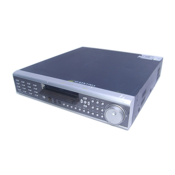
Ganz digimaster DR-8FX5 설치 매뉴얼 - 페이지 14
{카테고리_이름} Ganz digimaster DR-8FX5에 대한 설치 매뉴얼을 온라인으로 검색하거나 PDF를 다운로드하세요. Ganz digimaster DR-8FX5 18 페이지. 8ch / 16ch digital video recorder 960 h
Ganz digimaster DR-8FX5에 대해서도 마찬가지입니다: 설치 매뉴얼 (18 페이지)

INSTALLATION
Alarm I/O Connection
To connect the Alarm input signal
Connect the signal line of an alarm input device such as sensor to rear [ALARM IN] port
1.
Loosen screws on [IN1] through [IN16] port and [GND] port of the provided terminal
block.
2.
Insert one end of alarm signal cable alarm input terminal hole below the screw hole,
and then fasten the screw.
3.
Insert ground signal wire into the hole of the [GND] port (shown also below the
screw), and tighten the screw.
4.
To check proper insertion of the cable, gently pull the cable and test whether it
disconnects. To disconnet the cable, loosen the screw and pull out the cable.
To connect the Relay/Alarm output signal
Connect the signal line of an alarm output to rear [RELAY] port
1.
Loosen the screws on the [NO] or [NC] port and [COM] port of the provided
terminal bloack.
2.
Insert the alarm signal wire into the hole of the [NO] or [NC] input prot (shown
below the screw), and tighten the screw.
Check the relay type befere selecting a proper
NO (Normal Open) : normally Open but switching to Close if an alarm out occurs.
COM : Insert the grounding wire.
NC (Normal Close) : Normally Close but switching to Open if an alarm out occurs.
3.
Insert the ground signal wire into the hole of the [COM] port and tighten screw.
Or, you can connect the signal cable of the alarm output device to the [ALARM OUT].
1.
Loosen screws on [AO1] through [AO8] port and [GND] port of the terminal block.
2.
Insert the alarm signal wire into the hole of the AO port and tighten the screw.
3.
Insert the ground signal wire into the hole of the [GND] port and tighten the screw.
4.
To check proper insertion of the cable, gently pull the cable and test whether it
disconnects. To disconnet the cable, loosen the screw and pull out the cable.
5.
Install the wire-connected terminal block in the rear port.
14
