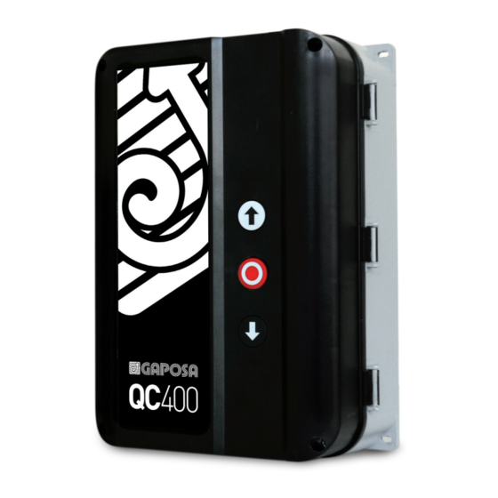
GAPOSA QC400 매뉴얼 - 페이지 13
{카테고리_이름} GAPOSA QC400에 대한 매뉴얼을 온라인으로 검색하거나 PDF를 다운로드하세요. GAPOSA QC400 16 페이지. Automatic control unit for three/single-phase motors with digital or mechanical limits

8 PLUG-IN RADIO RECEIVER QCMR500 (OPTIONAL)
The control can be radio operated thanks to the QCTE transmitter that allows the storage of 1997 radio codes.
The QCTE transmitter must be matched to the QCMR500 radio receiver, already inserted into the related slot (see page 5).
Set DIP7 in ON (GO Special functions - see par. 10).
Please look at the QCMR500 instructions to connect it to the control unit and to match it to the transmitter.
12 11 10 9 8 7 6 5 4 3 2 1
1
2
3
1 2 3 4 5 6 7 8 9 10
PLUG-IN RADIO
4
RECEIVER
5
QCMR500
6
7
8
9
10
11
9 PLUG-IN TRAFFIC LIGHT QCLSM (OPTIONAL)
12
13
This is a plug-in board to be used with the QC400 in order to control flashing lights, courtesy lamps or traffic lights during
14
the operation of the door or shutter.
Connect the QCLSM to X10. The possible operation options are described in the QCLSM instruction manual.
15
Radio plug-in terminals:
Pin 1 = output signal to board "Go function" (+24V)
Pin 2 = connected to board +24V after stop circuits
Pin 3 = Not connected.
Pin 4 = connected to board +24V after stop circuits
Pin 5 = connected to GND on board. (supply)
Pin 6 = connected to +24 power on board (supply)
Pin 7 – 10 = Not connected.
NOTE: the entrance "GO" (terminals 11-12 on X5) follows the
same logical of functioning selected for radio receiver.
POWER
SUPPLY
230V~
RED
LIGHT
GREEN
LIGHT
MOLEX CONNECTOR
13
