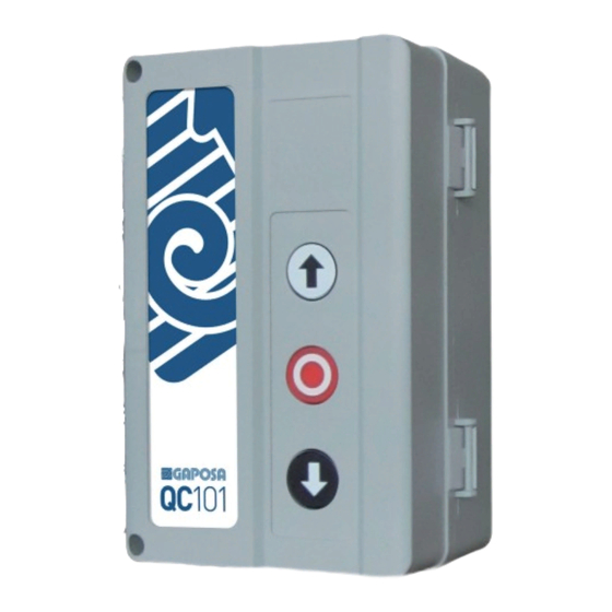
GAPOSA QC101 사용 설명서 - 페이지 3
{카테고리_이름} GAPOSA QC101에 대한 사용 설명서을 온라인으로 검색하거나 PDF를 다운로드하세요. GAPOSA QC101 16 페이지. Single-phase control unit

SAFETY
These instructions contain important information on the installation
and the use of the QC100/101 unit. Please keep them even after
installation. Do not start installing the QC100/101 unit without having
first read these instructions. The installation can only be done by
a qualified technician. In order to conform to the rules in force,
the installation must include on its power supply line a differential
magnetothermic switch with minimum distance between the contacts
of at least 3mm. The security of the product depends on a correct
installation. Be at a far distance from shutter/awnings in movement.
Check frequently if any loss of balance, sign of wear or damages wires
are shown. Do not use if any repairing or maintenance is needed.
GAPOSA declines all responsibility in case of improper use of the
product or of an incorrect installation. The product has been made
respecting the European norms: 2006/95/CE (CEE73/23, CEE93/68),
2004/108/CE (CEE89/336), CEE89/106, CEE89/392, EN60335-1
04/1998, EN60204-1 09/1993, EN55014-1 4/1998.
IMPORTANT! All connections must be made while power supply is
cut off!
TURN THE MAIN SWITCH OFF before any other operation!
Power supply
Max Motor power
Exit 24V~
Exit 12Vcc
AUX exit
Frequency
Coverage (int/ext)
Channels
Flashing light
Protection fuse
Protection rate
Working temperature
Dimensions
Maximum current (12V / 24V~)
Loading condition
Case 1
Case 2
Case 3
230 Vac ± 10% - 50/60Hz (singlephase)
800 W
terminals 11 - 12, MIN 20 Vac, MAX 26.5 V~
terminals 9 (+) - 3 (GND), MIN 9.5V, MAX 12.5 V
terminals 13 - 14, 250V - 2A, resistive load - potential-free
contact NO
433.92 MHz
20 m / 200 m
62
230 V~ - Max 25 W (autolamping)
4A (delayed)
IP54
-10°C / +50°C
133 x 208 x 80 mm
24V~
12Vcc
0mA
50mA
70mA
40mA
140mA
10mA
