GAPOSA M30A 참조 매뉴얼 - 페이지 8
{카테고리_이름} GAPOSA M30A에 대한 참조 매뉴얼을 온라인으로 검색하거나 PDF를 다운로드하세요. GAPOSA M30A 14 페이지. Safety brake
GAPOSA M30A에 대해서도 마찬가지입니다: 참조 매뉴얼 (11 페이지)
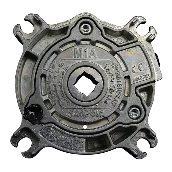
2. The safety brake must be always installed with the arrow pointing to the direction in
which the shutter descends; M1A and P200 safety brakes lock in both directions and
for this reason they can an indifferently be installed on the right or on the left side of
the shaft;
3. M1A and P200 safety brake must be installed in square and with the cable on the top
(Fig.1), the safety brakes base (from M3A to M30A) must be installed as horizontally
as possible; all safety brakes must be in square as regards the vertical level (perpen-
dicularly with respect to the shutter's shaft); in both directions any deviation must
not exceed ±3° (fig.1). A wrong horizontal or vertical alignment may vary the locking
speed and may cause a bad operation of the system;
4. For the base use fastening screws (n. 4 for M1A/P200 and n.2 screws for the other
models) with a suitable diameter (ref. Tab. B);
5. Weld the support pins of the shaft concentrically to it;
6. Insert the shaft support pin (with key or square in case of M1A and P200) into the
safety brake hole smoothly; eventually check the alignment between the safety brake
hole, on one side, and the output shaft on the other side;
7. Avoid a snapping working of the shutter since it might cause the intervention of the
safety brake. A well-built side slide and good profiles assure a regular working of the
device;
8. Connect the safety brake electrical cable (complete with micro switch and NC con-
tact) to the STOP control in the motor control unit (P. 28);
During installation, in order to avoid bad performances of the safety brake, do not tam-
per the screws and the relative nuts on the central body; GAPOSA srl is not responsible
for damages caused by a wrong installation or an improper use.
TESTING INSTRUCTIONS
The testing process of the safety brake consists of:
1. An accurate check of a perfect installation, by making sure that all the fastening
screws of the base and of the safety brake are provided with suitable self- locking
washers and perfectly tightened. Make also sure that the safety brake has not been
unduly opened.
2. A check of the electrical continuity at the extremity of the micro-switch thread.
8