ALIBI ALI-NS2114L 빠른 설치 매뉴얼
{카테고리_이름} ALIBI ALI-NS2114L에 대한 빠른 설치 매뉴얼을 온라인으로 검색하거나 PDF를 다운로드하세요. ALIBI ALI-NS2114L 7 페이지. 4mp white light ip turret camera
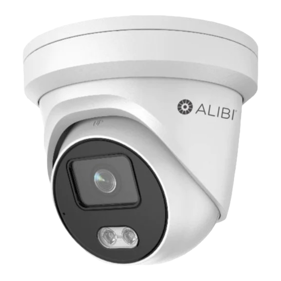
This document guides you through the basic steps to install and configure the ALI-NS2114L network
turret camera. This camera features:
1/1.8" 2688 × 1520 pixel (4 MP) Progressive Scan CMOS @ 30 fps
•
3000°K soft white light LED with 100 ft range (see Step 10 in the procedure below)
•
4 mm lens with 94° FOV
•
120 dB Wide Dynamic Range
•
Built-in Microphone
•
Built-in microSD/SDHC/SDXC slot, up to 128GB
•
H.265, H.265+, H.264+, H.264 video compression
•
IP66, IK10 vandal proof rated
•
Optional ALI-AB1 Alibi short wall mount bracket, ALI-AB2 Alibi long wall mount bracket,
•
ALI-AA1, ALI-AA2 brackets, ALI-AJ1 flange adapter
For more information, refer to these documents - available from your equipment vendor:
ALIBI™ Witness 2.0 r3 App for Android or iOS Quick Start Guide
•
ALIBI™ IP Camera Firmware Version 5.4 User Manual (or later) provided at:
•
AlibiSecurity.com/resources
Adapter plate
Trim ring
Built-in
microphone
Shroud
and turret
assembly
White light LEDs
Fixing screw
and tab
Holes for surface
mounting screws (3)
Ethernet RJ-45 (with PoE)
12 Vdc connector
1
www.observint.com
ALI-NS2114L 4MP White Light IP Turret Camera Quick Installation Guide
Cable channel Drop cable
Camera assembly
turret assembly
Holes for bracket
mounting screws
Cable channel
Cable channel
Adapter plate
Drop cable connectors
What's in the box
Your camera includes the items shown below:
Security L-wrench
•
Mounting hardware - four screws and
•
wall inserts
Drill template
•
Waterproof Ethernet Fitting
•
Installation and setup instructions
•
Step 1.
Route wiring to the camera
Interface cables can be routed into the camera either through the adapter plate (through the mounting
surface) or through the cable channel on the side of the camera.
When selecting a mounting location for the camera
• Make sure that there are no reflective surfaces near to the camera lens. Light from the camera may
NOTE
• Determine how interface wiring are routed into the camera. The cable can be routed through the
The camera includes connectors for the following:
Ethernet (required): The Ethernet drop cable can connect to a LAN extension cable from a
•
switch or Network Video Recorder. The camera can be powered across the LAN using power over
Ethernet (PoE) injection. See the Specifications section at the end of this document for power
requirements. A weatherproof Ethernet Fitting is provided.
12 Vdc power input (optional if PoE powered, required if not): If powering the camera
•
with a long power extension cable, refer to the tables at the end of this guide for wire gauge
requirements. Voltage input at the camera can be within the range 12 Vdc ± 25%.
Maintenance
panel with
1.
Route a LAN extension cable from a network switch or Network Video Recorder to where the
microSD slot
camera will be installed.
and Reset*
2.
If the camera is not powered using PoE, route 12 Vdc power cables from an adequate power
Turret "UP"
source to the location where the camera will be installed. Voltage input at the camera can be
orientation
within the range 12 Vdc ± 25%.
Step 2.
Remove the Adapter plate
To remove the adapter plate:
1.
Set the camera base down on a clean surface.
Lens
Tabs to hold
Trim ring
plug
2.
Rotate the trim ring counter-clockwise as shown in the picture above (about 30°), and then lift it
off of the camera assembly.
3.
Using the security L-wrench, fully loosen the fixing screw (captive screw). See photo above.
bounce back onto the lens causing reflections.
mounting surface and access hole in the mounting plate or through the side inlet.
Shroud and turret assembly
Fixing screw (loosened)
and tab
Lip
Adapter plate
ALI-NS2114L_CQ
190603