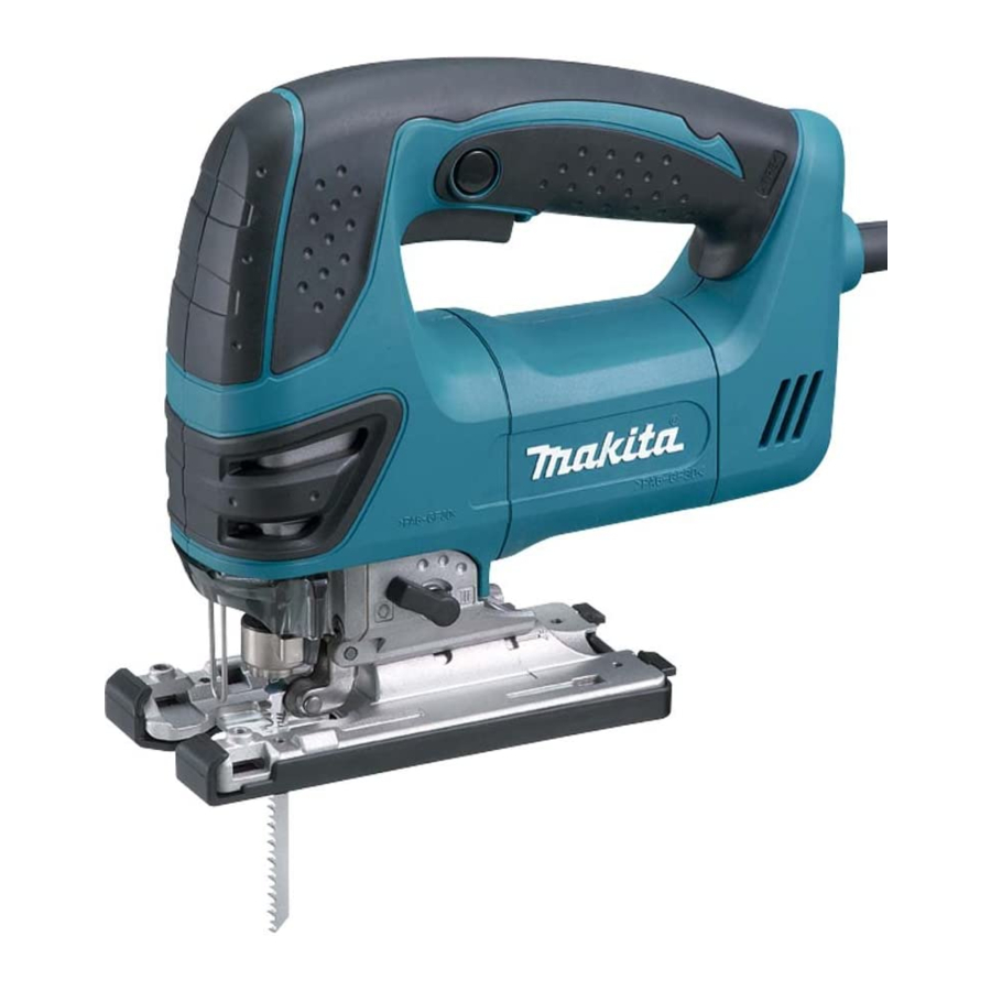
Makita 4350T 기술 정보 - 페이지 3
{카테고리_이름} Makita 4350T에 대한 기술 정보을 온라인으로 검색하거나 PDF를 다운로드하세요. Makita 4350T 14 페이지. Jig saw
Makita 4350T에 대해서도 마찬가지입니다: 사양 (2 페이지), 사용 설명서 (13 페이지), 사용 설명서 (13 페이지), 사용 설명서 (13 페이지)

R
epair
[2] Disassembling Tool opener
1. Remove M5x18 Hex socket head bolt. Base is separated from product. (Fig. 1)
2. Remove M4 + Pan head screw. Tool opener and Torsion spring 6 are separated. (Fig. 2)
Fig. 1
M5x18 Hex
socket head bolt
[3] Assembling tool opener
1. Install Torsion spring 6 into the depression on Gear housing cover around Tool opener hinge portion, and then fasten
Tool opener to Gear housing cover with M4 + Pan head screw.
2. Turn the tail of Torsion spring 6 clockwise using thin flat screwdriver to set it in place. (Fig. 3)
Fig. 3
Viewed from Blade holder side
Gear housing
Blade holder
[4] Disassembling Handle section
1. Separate Handle R from Housing L by the following steps.
(1) Remove Tapping screws as illustrated in Fig. 4.
(2) Gently lift up the 4x50 Tapping screw installation side of Handle R with slotted screwdriver to remove the hooks of
Handles L and R from the notch of Motor housing. (Fig. 5)
Note: Take care not to break the hooks, the protrusion and the depressions when disassembling.
2. LED circuit (only for 4350FCT) and Safety wire can be removed together. As for removal of Safety wire, open Tool
opener and remove both tails of Safety wire from the holes of Gear housing cover behind Handles L and R.
Fig. 4
4x18 Tapping screw
Tool opener
Base
Tool opener
The tail of
torsion spring 6
Gear housing cover
4350T, 4350CT: 4x18 Tapping screw
4350FCT: 4x40 Tapping screw
4x50 Tapping screw
(Refer to Fig. 5.)
Safety wire
Fig. 2
Torsion spring 6
Tool opener
M4 + Pan head screw
Tool opener hinge portion
Fig. 5
Notch of Motor housing
Slotted screwdriver
P 3 / 14
M4 + Pan head screw
Hook of Handle L
Hook of
Handle R
4x50 Tapping screw
installation hole
