CORNING EDC-02P-NH 매뉴얼 - 페이지 9
{카테고리_이름} CORNING EDC-02P-NH에 대한 매뉴얼을 온라인으로 검색하거나 PDF를 다운로드하세요. CORNING EDC-02P-NH 12 페이지. Environmental distribution center
CORNING EDC-02P-NH에 대해서도 마찬가지입니다: 매뉴얼 (7 페이지)
SRP 003-304 • Issue 9 • July 2004
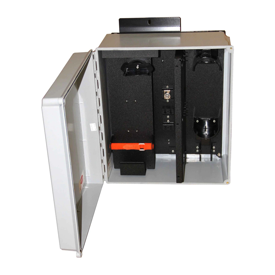
11.4 As you complete a splice, label the
connector end of the pigtail with its port
identifier. Record information appropriately on
the record label inside the front door
(Figure 17).
11.5 Repeat for all required splice trays.
NOTE: Accurate record keeping is imperative
for an organized installation.
11.6 Once all splicing is complete, route the
buffer tubes and pigtails around the radius
control guides as shown in Figure 18. Route the
buffer tubes as shown in order to maintain the
appropriate bend radius to the connector panel.
11.7 Secure the splice tray to the wall as shown
in Figure 18. Discard spacers as required for the
type of tray installed.
12. Installing BTF Kits
12.1 Fiber optic cable can be installed using
Corning Cable Systems BTF kits.
12.2 Route the buffer tubes twice around the
radius guides in a counterclockwise direction.
Mark the location of the mounting bracket on
the buffer tubes as shown in Figure 19 to
determine the length required.
Figure 17
12.3 Install fan-out assemblies and connectors
according to the instructions provided with the
BTF kits.
12.4 Route the buffer tubes around the radius
guides and secure the fan-outs to the fan-out
bracket as shown using a cable tie (Figure 20).
Figure 18
Page 9
Figure 19
Figure 20