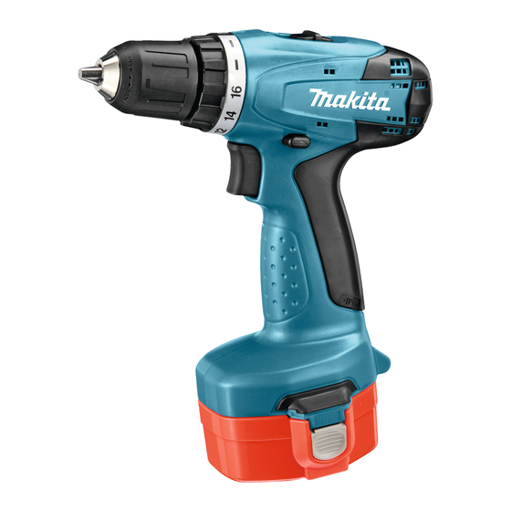
Makita 6391D 기술 정보 - 페이지 7
{카테고리_이름} Makita 6391D에 대한 기술 정보을 온라인으로 검색하거나 PDF를 다운로드하세요. Makita 6391D 7 페이지.
Makita 6391D에 대해서도 마찬가지입니다: 사용 설명서 (8 페이지)

W
iring diagram
Fig. D-2
DC Motor has to be so
assembled to Housing set (L)
that its Red point mark
is positioned on the back
bone side of the machine.
Fig. D-2A.
Connect Switch's Lead wire (black) to
Battery holder while facing it to rear side.
This protruded Side is fitted
to Housing set (R).
Housing set (L)
Rear view of
Housing set (L)
DC Motor
Switchs' Lead wires (black, red)
have to be fixed with Lead wire
holder.
Battery holder
Switch's Lead
wire (black)
Rear side
Red point
mark
Switch's lead
wire (black)
Rear side
Battery holder
Front side
Connect Switch's Lead wire (red) to
Battery holder while facing it to front side.
Housing set (R) Side
P 7/ 7
Switch's lead
wire (red)
Front side
Switch's Lead
wire (red)
