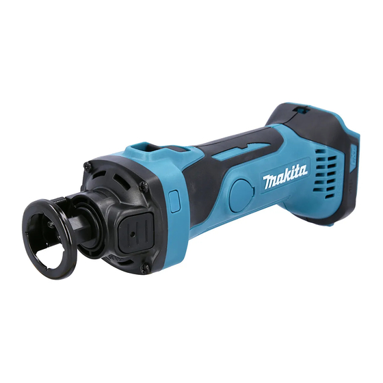
Makita DCO140 기술 정보 - 페이지 7
{카테고리_이름} Makita DCO140에 대한 기술 정보을 온라인으로 검색하거나 PDF를 다운로드하세요. Makita DCO140 8 페이지. Cordless cut-out tool
Makita DCO140에 대해서도 마찬가지입니다: 사용 설명서 (13 페이지), 사용 설명서 (13 페이지)

C
ircuit diagram
Fig. D-1
Receptacles
Terminal
black
How to Check the Switch Condition
1. Unscrew the two screws or disconnect the two receptacles.
(If not, the Switch condition cannot be judged correctly because current flows through Controller.)
2. Check the condition between the terminals (shown below) with a tester (Makita part No. 1R402).
Good condition
Terminals
Switch condition
OFF
ON
• Either of the two red lead wires from Terminal and
Controller can be connected to either 1 or 2 .
• Either of the two red lead wires from Terminal and
Controller can be connected to either
red
red
red
red
yellow
Controller
and
and
∞ )
∞ )
O.L (
O.L (
Ω or less
Ω or less
0.1
0.1
Switch
Pan head screws
Insulated terminals
red
black
or
.
Endbell complete
viewed from rear side
red
Line filter
(if used)
Connectors
P 7/ 8
