Jandy Jandy Pro Series 설치 및 운영 매뉴얼 - 페이지 7

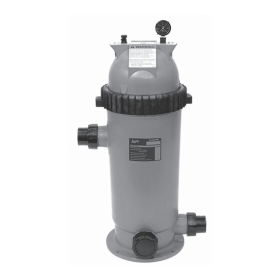
{카테고리_이름} Jandy Jandy Pro Series에 대한 설치 및 운영 매뉴얼을 온라인으로 검색하거나 PDF를 다운로드하세요. Jandy Jandy Pro Series 20 페이지. Single element cartridge pool & spa cs filters
Jandy Jandy Pro Series에 대해서도 마찬가지입니다: 소유자 매뉴얼 (12 페이지), 설치 매뉴얼 (16 페이지), 설치 및 운영 매뉴얼 (20 페이지), 소유자 매뉴얼 (20 페이지), 매뉴얼 (8 페이지), 빠른 시작 매뉴얼 (2 페이지), 설치 지침 (2 페이지), 설치 및 운영 매뉴얼 (16 페이지), 설치 및 운영 매뉴얼 (16 페이지), 설치 및 운영 매뉴얼 (16 페이지)

Jandy Jandy Pro Series 설치 및 운영 매뉴얼
Jandy Pro Series Levolor
II Electronic Water Leveler
®
Models K-2100

Section 3. Installation Instructions

3.1

Materials and Tools

Installation Materials Furnished for
Levolor II, Model K-2100
Three-probe Sensor with Wire
24VAC Solenoid Valve
1" Coupler
Control Box (K-2100)
Remote Sensor Housing
Hardware Kit
Grease-Filled Wire Nuts for Valve
Screws
Anchors
Owner's Manual - Warranty Information
Additional Materials Needed for Installation
DPST (Dual Pole Single Throw) 24VAC Relay with
Contacts Properly Rated for Pump Selected
Anti-Siphon Valve*
2-Conductor 18-Gauge Solid-Core Burial Cable
Wire-Nut Connectors for the Sensor, Relay, and
Power Connections.
*The anti-siphon valve is not necessary if the
connection is made from the irrigation system.
Open the box and check to see that it contains the
contents listed above. If it does not, contact your Jandy
dealer or Zodiac Pool Systems, Inc. technical support at
1 (800)-822-7933.
|
Installation and Operation Manual
Fill Line
Qty
1
1
1
1
1
1
2 per kit
4 per kit
4 per kit
Figure 2. K-2100 Installation
1
3.2

Installing the Control Box

1.
Mount the control box to the wall near the pump
and filter. See Figure 2. Do not install the control
box within 10 feet (3 meters) of the pool edges.
2.
Mount the control box at eye level. Leave
sufficient clearance on all sides of the chassis
backplate.
3.
Check the source voltage. (The unit is factory
wired for 220 volt operation.) To modify the
wiring for 110 volt operation, see Section 3.3,
Changing Wiring for 110 Volt Operation.
4.
For 220 volt operation, connect the black wire to
line 1 and connect the black wire with the yellow
stripe to line 2. See Figure 3.
Ground
Figure 3. Factory Wiring for 220 Volt Operation
ENGLISH
Transformer
5
2
1
6
Line 2
Line 1
Page 7