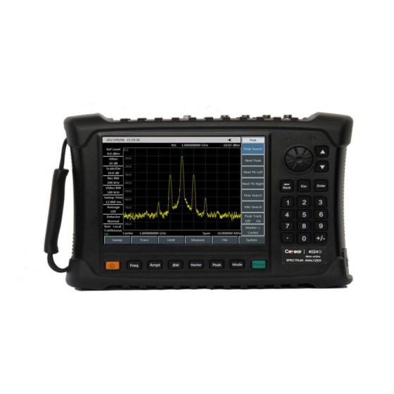
Ceyear 4024D 유지 관리 매뉴얼 - 페이지 16
{카테고리_이름} Ceyear 4024D에 대한 유지 관리 매뉴얼을 온라인으로 검색하거나 PDF를 다운로드하세요. Ceyear 4024D 19 페이지. Spectrum analyzer

Set the path, click "Set Path", and select the path of the DAC and temperature compensation file,
e)
and then the follow-up measurement DAC file, 4024 test file as well as the compensation file will be
placed into a folder with the name of the spectrometer serial number.
f)
Check 4024 series spectrum analyzer to ensure that there are no IF DAC files and compensation
files. If a DAC or compensation file exists, it shall be deleted firstly. The specific operation is as
follows: Connect the PC with the 4024 spectrum analyzer with a point-to-point network cable, open
the 4024 host folder: "ftp://172.141.xx.xx/" in PC browser, delete tc.tcdoc and IFGainAtten.dc in the
MMCMemory folder, and then restart the spectrum analyzer.
Attention: The IP address of the 4024 spectrometer and PC shall be located on the same network
segment. If they are different, the IP of the computer or spectrometer shall be set to make it within the
same network segment (for example, if the IP of the spectrometer is 172.141.11.202, the IP of the
computer shall be set to 172.141.11.xx).
Connect the computer with the spectrum analyzer with a point-to-point network cable; connect the BNC
cable with 10 MHz reference input of the spectrometer and 10 MHz reference output of the signal
source, and then connect the cable connected with the power meter sensor in steps c) and d) with the
RF input port of the spectrometer, as shown in the above figure. Click Calibration Spetrum, and when the
calibration is completed, it will prompt that the "IFGainAtten.dc" file will be generated. This file is in the
folder with the name of the serial number created in step e).
g)
Keep the connection mode in step 7 unchanged and click the Measure Spetrum, and the
compensation program will carry out 4024 preamplifier OFF and preamplifier OFF data test, the
screen will prompt the current measurement tasks, and it will prompt to generate the "tc.tcdoc" file
Fig. 13 Finish of Calibration Signal Source
GPIB card
10MHz out
Signal source
Network cable
PC
Fig. 14 Measure Spectrum Analyzer
BNC cable
Adapter
2.4 mm cable
Adapter
Spectrum analyzer
10MHz in
