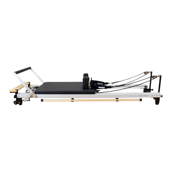
Align-Pilates C Series 조립 지침 및 사용자 설명서 - 페이지 4
{카테고리_이름} Align-Pilates C Series에 대한 조립 지침 및 사용자 설명서을 온라인으로 검색하거나 PDF를 다운로드하세요. Align-Pilates C Series 12 페이지. Reformer

5. Insert the Reformer Carriage
With the reformer back on the floor, firstly remove the 2 rubber carriage stoppers from the end of the runners (Fig. 7).
Carefully remove the carriage bed from its packaging. Note: two of the wheels are on floating axles wheels which
allow the carriage to self-center, aiding the smooth running of the reformer, remove these two wheels from their seper-
ate packaging and insert into the carriage (Fig. 5) - be careful not to tip the carriage or these wheels can slide out (Fig
6). With one person holding each side of the carriage bed, gently slide the carriage in to the
runners (Fig. 5) with the springs pointing towards the standing platform & attach at least one spring- care must be
taken to align the floating wheels with the C shape runner channel when inserting the carriage in to the runners to
prevent damage to the wheels. Note: when removing the carriage for maintenance be careful not to let the wheels
Fig.5
6. Runner stoppers
Having installed the carriage now screw the stoppers back in hand
tight. The stoppers prevent the carriage from hitting the rope risers and
are designed to allow for quick removal of the bed for cleaning &
maintenance, (Fig.7). Simply unscrew to get access and ensure you
re-screw them back in before use.
7. Offset Shoulder rests
Insert the shoulder rests into each of the shoulder rest receiving holes
on the carriage bed (Fig. 8). They can be locked in place by placing
the locking pin through the hole at the bottom of the chromed bar (Fig.
9). The locking pins are attached on a string to the underside of the carriage as shown in Fig 9.
Please note the new design of shoulder rests have one side offset, this means you have a choice of a narrower or
wider position for the shoulder rests, according to how you insert them. See Fig. 10 & 11.
4
Fig.6
Fig.8
Fig.10
End Stopper
Fig.7
Fig.9
Fig.11
