Garmin ECHOMAP Ultra Series 설치 지침 - 페이지 2
{카테고리_이름} Garmin ECHOMAP Ultra Series에 대한 설치 지침을 온라인으로 검색하거나 PDF를 다운로드하세요. Garmin ECHOMAP Ultra Series 4 페이지. Marine gps chartplotters
Garmin ECHOMAP Ultra Series에 대해서도 마찬가지입니다: 설치 지침 (4 페이지)

2
1
Using a 13 mm (
/
in.) drill bit, drill one or more of the holes
2
inside the corners of the solid line on the template to prepare
the mounting surface for cutting.
3
Using a jigsaw or rotary cutting tool, cut the mounting surface
along the inside of the solid line indicated on the template.
4
Place the device into the cutout to test the fit.
5
Use a pry tool, such as a flat piece of plastic or a screwdriver,
to carefully pry up the corners of the trim caps, and remove
the trim caps.
6
Place the device in the cutout, and ensure the mounting
holes on the device line up with the pilot holes on the
template.
7
If the mounting holes on the device do not line up with the
pilot holes on the template, mark the new hole locations.
8
1
Using a 3.2 mm (
/
in.) drill bit, drill the pilot holes.
8
9
Remove the template from the mounting surface.
10
Place the device in the cradle
Cradle, page
3).
11
Install the rubber gasket
The rubber gasket has adhesive on the back. Make sure you
remove the protective liner before installing it on the device.
12
Connect all necessary cables
and spin the locking rings clockwise to secure the cables to
the cradle before placing it into the cutout.
To prevent corrosion of the metal contacts, cover unused
connectors with weather caps.
13
Place the device into the cutout.
14
Secure the device to the mounting surface using the included
screws.
15
Install the trim caps by snapping them in place around the
edges of the device.
Connection Considerations
After connecting the cables to the cradle, tighten the locking
rings to secure each cable.
Connector View
2
(Installing the Device in the
on the back of the device.
(Connector View, page
NOTICE
Item Label
POWER
12 PIN XDCR 12-pin transducer
LVS XDCR
NMEA 2000
NETWORK
To prevent corrosion of the metal contacts, cover unused
connectors with weather caps.
To comply with regulations and to reduce noise, snap the ferrite
beads on the network and transducer cables, near the
connectors.
Power and Data Cable
• The wiring harness connects the device to power and NMEA
0183 devices.
• If you are not connecting NMEA 0183 devices, disregard the
blue and brown wires.
• The device has one internal NMEA 0183 port that is used to
connect to NMEA 0183 compliant devices.
• If it is necessary to extend the power and ground wires, you
must use 1.31 mm
• If it is necessary to extend the NMEA 0183 or alarm wires,
you must use .33 mm
Item
Wire Function
NMEA 0183 internal port Rx (in)
2),
NMEA 0183 internal port Tx (out)
Ground (power and NMEA 0183)
Power
Connecting to Power
When connecting the power cable, do not remove the in-line
fuse holder. To prevent the possibility of injury or product
damage caused by fire or overheating, the appropriate fuse
must be in place as indicated in the product specifications. In
addition, connecting the power cable without the appropriate
fuse in place voids the product warranty.
You should connect the red wire to the same battery through the
ignition or another manual switch to turn the device on and off.
1
Route the power cable between the power source and the
device.
2
Connect the red power wire to the ignition or another manual
switch, and connect the switch to the positive (+) battery
terminal if necessary.
3
Connect the black wire to the negative (-) battery terminal or
to ground.
4
Connect the power cable to the device, and turn the locking
ring clockwise to tighten it.
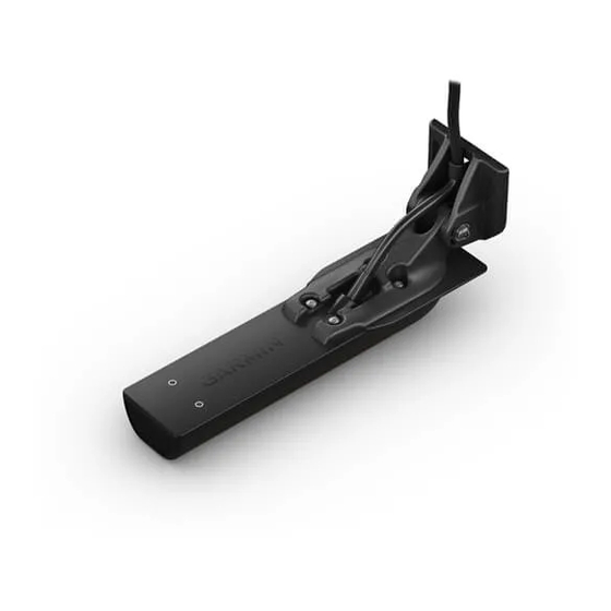
Connecting the Device to a Transducer
Go to
garmin.com/transducers
dealer to determine the appropriate type of transducer for your
needs.
Description
Power and NMEA
0183 devices
®
Panoptix
LiveScope
LVS12 12-pin transducer
™
™
NMEA 2000
network
®
ECHOMAP network for sonar sharing
Ground screw
NOTICE
2
(16 AWG) or larger wire.
2
(22 AWG) wire.
WARNING
or contact your local Garmin
Wire Color
Brown
Blue
Black
Red
