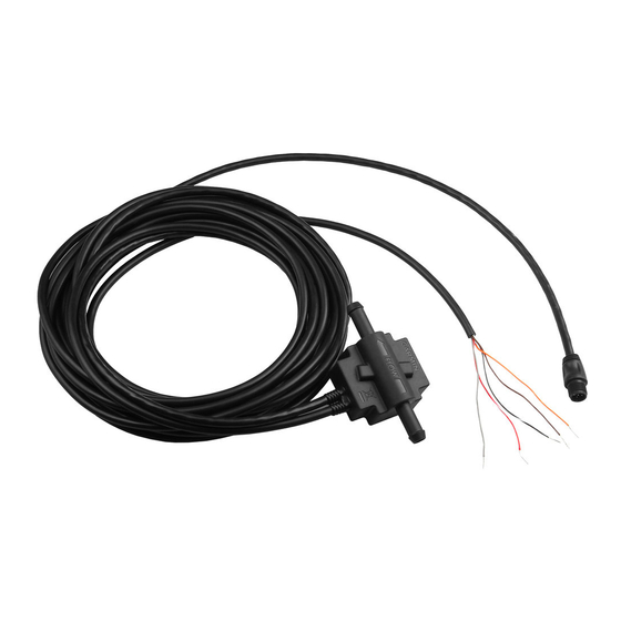
Garmin GFS 10 - Fuel Sensor 설치 지침 매뉴얼 - 페이지 2
{카테고리_이름} Garmin GFS 10 - Fuel Sensor에 대한 설치 지침 매뉴얼을 온라인으로 검색하거나 PDF를 다운로드하세요. Garmin GFS 10 - Fuel Sensor 49 페이지. Fuel sensor
Garmin GFS 10 - Fuel Sensor에 대해서도 마찬가지입니다: 빠른 참조 매뉴얼 (24 페이지), 기술 참조 (30 페이지), 설치 지침 매뉴얼 (44 페이지), 중요 안전 정보 (48 페이지), 구성 매뉴얼 (2 페이지), 적합성 선언 (1 페이지)

I
I
nstallatIon
nstructIons
Step 1: Installing the GFS 10 in the Fuel Line
Ensure the fuel line is drained, and use a hose cutter or knife to cut the fuel line where you want to install the GFS 10. Use the included hose
clamps to secure the fuel line to the GFS 10. Do not over-tighten the clamps. Inspect your fuel system and connections regularly.
Notes:
•
Install the GFS 10 as far from the engine as practical.
Do not install the GFS 10 directly on the engine or
where it could be subjected to excessive heat or
vibration. Do not install the GFS 10 between the
engine and the priming bulb (if applicable).
•
When placing the GFS 10 in the fuel line, be sure
the direction of flow, as indicated by the arrow, points
toward the engine.
•
Install the GFS 10 so the fuel flows in an upward
direction through the GFS 10. This will prevent errors caused by air bubbles.
•
Install the GFS 10 in a location above the maximum fuel level of the fuel tank.
•
Install the included fuel filter in the fuel line between the fuel tank and the GFS 10. Always have a spare metal
available.
•
If additional fuel hose is needed when installing the GFS 10 and fuel filter, use
" (9.5 mm) in-line fuel-line splice barbs available. This allows you to remove the GFS 10 and the fuel filter, in case of an
•
Have two
3
/
8
emergency, and maintain normal engine operation.
•
Be sure to clean up any spilled fuel.
Step 2: Mounting the GFS 10 and Fuel Filter
The GFS 10, the in-line fuel filter, and the fuel hoses must be mounted to your boat. A bracket for the GFS 10, cable ties
with eyelets for the in-line fuel filter and hoses, and mounting screws are provided.
When mounting the GFS 10 to a solid structure on your boat, use included the bracket to secure the GFS 10 device, and
use two included cable ties to secure the hose on either side of the GFS 10. When mounting the in-line fuel filter to a
solid structure on your boat, use two cable ties around the fuel filter, and two cable ties around the hose on either side of
the fuel filter.
Use the included screws to mount the GFS 10 and the in-line fuel filter. Use the Drill Size Table to determine the
appropriate pilot hole.
Material
Material Thickness (in.) Material Thickness (mm)
Aluminum alloy
from
sheet metal
from
Plywood (resin impregnated) -
1
/
'' to
5
/
''
from 0.76 to 2.03
32
64
/
'' to
/
''
from 2.28 to 9.52
3
3
32
8
Professional installation recommended
Engine
Engine
To power and
To power and
data connections
data connections
"
/
3
8
Hole Size (in.)
Hole Size (mm)
1
/
''
3.25 mm
8
/
''
3.73 mm
47
64
/
''
3.66 mm
9
64
Drill Size Table
GFS 10
GFS 10
Fuel filter
Fuel filter
(9.5 mm) US Coast Guard type A1 fuel hose.
Hole Size
(Drill Number)
30
26
27
GFS 10 Installation Instructions
Fuel tank
Fuel tank
"
/
3
in-line fuel filter
8
Bracket
Bracket
Cable
Cable
tie (×6)
tie (×6)
