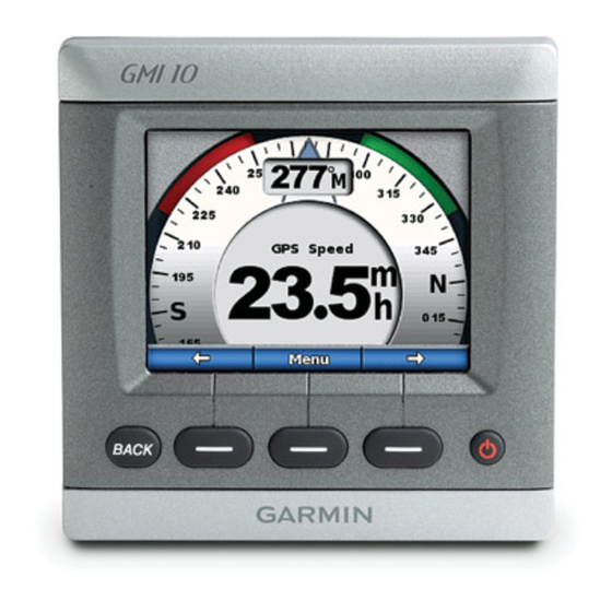
Garmin GMI 10 설치 지침 매뉴얼 - 페이지 3
{카테고리_이름} Garmin GMI 10에 대한 설치 지침 매뉴얼을 온라인으로 검색하거나 PDF를 다운로드하세요. Garmin GMI 10 8 페이지. Flush moun template
Garmin GMI 10에 대해서도 마찬가지입니다: 빠른 시작 매뉴얼 (20 페이지), 설치 지침 매뉴얼 (8 페이지), 템플릿 (1 페이지), 지침 (2 페이지), 빠른 시작 매뉴얼 (21 페이지), 설치 지침 매뉴얼 (8 페이지)

7. Using a drill bit as specified by the Pilot Hole Size Table, drill the four mounting holes.
Material
Material Thickness (in.)
Aluminum alloy
sheet metal
Fiberglass—all thicknesses
High Density Plastic—all thicknesses
Plywood (resin impregnated)—Professional installation recommended
NOTE: If you are mounting the chartplotter in fiberglass, it is recommended to use a countersink bit to drill a clearance-
counterbore through only the top gel-coat layer. This will help to avoid any cracking in the gel-coat layer when the screws are
tightened
8. Place the GMI 10 into the cutout
9. Securely tighten the four mounting screws through the GMI 10 into the drilled mounting holes.
NOTE: Stainless-steel screws may bind when screwed into fiberglass and overtightened. Garmin recommends applying an
anti-galling, stainless anti-seize lubricant to the screw before using.
10. I nstall the mounting covers by snapping them into place.
Step 3: Connect the GMI 10 to Power
The GMI 10 comes with a cable assembly that connects it to power and provides interface capabilities for connecting
external devices with NMEA 0183
The replacement fuse is an AGC/3AG – 1 A fuse. If it is necessary to extend the power wires, use 18 AWG wire. If your
boat has an electrical system, you might be able to wire the GMI 10 directly to an unused holder on your current fuse
block. If you are using the fuse block, remove the in-line fuse holder supplied with the GMI 10. You can also wire the
GMI 10 directly to the battery.
Boat ground
-
+
To GMI 10
CAuTION: The GMI 10 maximum input voltage is 32 Vdc. Do not exceed this voltage, because this can damage the GMI
10 and void the warranty.
NOTE: During a typical installation, use only the red and black wires. The other wires are used for NMEA 0183 connections,
and do not have to be connected for normal operation of the GMI 10. For information on connecting to a NMEA 0183-
compatible device, see
GMI 10 Installation Instructions
Material Thickness (mm)
from
/
to
/
1
5
32
64
from
/
to
/
3
3
32
8
Pilot Hole Size Table
(page
6).
1 A fuse
page 6.
Hole Size (in.)
from 0.76 to 2.03
from 2.28 to 9.52
1A
Fuse Block
I
nstallatIon
Hole Size (mm)
.128
3.25
.147
3.73
.140
3.56
.125
3.17
.144
3.66
To 8– Vdc boat
supply
I
nstructIons
Hole Size
(Drill Number)
30
26
28
1
/
8
27
