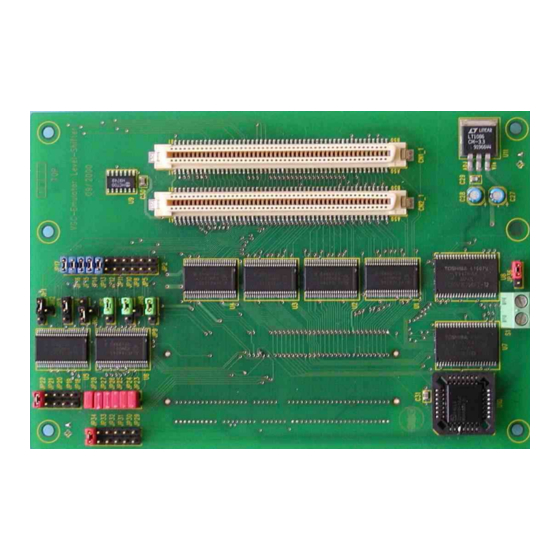
Fujitsu MB91360 SERIES 사용자 설명서 - 페이지 6
{카테고리_이름} Fujitsu MB91360 SERIES에 대한 사용자 설명서을 온라인으로 검색하거나 PDF를 다운로드하세요. Fujitsu MB91360 SERIES 17 페이지. Levelshifter board
Fujitsu MB91360 SERIES에 대해서도 마찬가지입니다: 사용자 설명서 (43 페이지), 애플리케이션 노트 (35 페이지), 사용자 설명서 (20 페이지)

Chapter 1 Interfacing the MB91360 Starter Kit to the STARTERKITMB91360-ADA120 and probe Cable
1 Interfacing
STARTERKITMB91360-ADA120 and probe Cable
The MB91F367/8 is a 120-pin derivative of the MB91360 family processors. The
MB91F367/8 is packaged in the FTP-120P-M21.
In order to allow users to develop applications on the MB91360 Starter Kit, an adaptor board
and Probe Cable have been developed.
The Adapter Board (STARTERKITMB91360-ADA120), which converts the MB91F362 in out
to the MB91F365/6/7/8 pin out, can be fitted to the Starter Kit with the use of Pin Headers.
For the Adapter board to be fitted correctly, the MB91F362 MCU and socket cap must be
removed from the Starter kit.
The Adapter Board is fitted with an NQPACK120SD enabling the user to fit either an MCU or
the Probe Cable. Jumpers J1 and J2 enable switching between sub clock and D/A Converter
on pins 27 and 28 – please see circuit diagram for details.
Jumper
JP1
JP2
Note: Default Jumper Setting: MB91F368G JP1, JP2 = 2-3
The Probe cable interfaces between the Emulator MB2197-01 and the NQPACK120SD.
Please note the direction of the probe cable when fitted onto the Starter Kit. The probe cable
is offset by 90° compared to the MB91FV360G.
Also included is a pin cross-reference between the MB91FV360, MB91F365/6 and
MB91F367/8.
The following diagram shows the starter kit assembled with the STARTERKITMB91360-
ADA120 Adapter board and probe cable.
UG-910002-15
STARTERKITMB91360-ADA120
the
MB91360
MB91F365G
MB91F366G
MB91F367G
MB91F368G
1-2
2-3
1-2
2-3
- 6 -
Starter
Kit
© Fujitsu Microelectronics Europe GmbH
to
the
