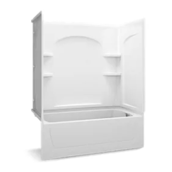
Kohler 71120122-0 설치 및 관리 매뉴얼 - 페이지 9
{카테고리_이름} Kohler 71120122-0에 대한 설치 및 관리 매뉴얼을 온라인으로 검색하거나 PDF를 다운로드하세요. Kohler 71120122-0 45 페이지.

Diagrama de instalación
¡IMPORTANTE! Todas las dimensiones son nominales. La tolerancia de abertura entre
los postes es de +1/8" (3 mm)/-0. Mida con cuidado el producto antes de determinar
las dimensiones del encajonado. Quizás sea necesario colocar cuñas entre la
estructura de postes de madera y la unidad. Si se requiere una pared resistente al
fuego, las dimensiones del diagrama de instalación deberán aumentar según el grosor
del material resistente al fuego. Las dimensiones de abertura entre los postes se deben
medir por el lado expuesto del material de la pared. Las dimensiones del diagrama
de instalación son cruciales para una correcta instalación. Construya la estructura y
coloque las tuberías con precisión.
En caso de instalar una puerta de ducha con esta bañera, consulte las instrucciones de
instalación del fabricante de la puerta para cualquier consideración especial de la
estructura de postes de madera.
Construct the Framing
NOTE: Refer to the "Roughing-In" section for dimensions.
Framing Provisions
WARNING: Risk of product and property damage. The bath must be supported
by the subfloor. The wall surrounds are not designed to hold the bath in place
and are not intended to be load bearing. The clips or roofing nails must be used
to prevent the bath from lateral movement.
The bath with apron must be attached to the studs on three sides.
A subfloor must be installed. The bath must be positioned to allow clearance for
drainage through the floor joists or slab and to allow convenient plumbing
installation.
Studs must be positioned roughly as shown in the "Roughing-In" section to
properly fasten the attachment clips or the bath flange. Other stud locations are
optional except for those which must meet the load-bearing requirements of local
building codes. Studs must also allow for the installation of plumbing fittings and
any shower door. Locate the shower door studs as required by the shower door
manufacturer.
For Bath Only without Wall Surrounds
Provide the necessary backing or support for shelving, grab bars, towel bars or
other accessories. Refer to the accessory manufacturer's instructions for proper
installation.
For Bath with Wall Surrounds
NOTE: If the wall surrounds will be installed to a masonry wall, make provisions for
plumbing connections. For the plumbing end wall, construct a separate frame wall a
minimum of 6" (15.2 cm) from the masonry wall. For the remaining walls, use 2x2
furring strips to provide stud locations.
Ensure that the outer stud is positioned with the vertical wall flanges 33-1/4" (84.5
cm) from the back wall. The outer edge of the stud should align with the edge of
the wall flange.
IMPORTANT! Accessories that require backing or support are not recommended for
this installation. Installing these accessories could void the warranty.
Ensure fiber or other soft insulation does not drop down into the water channel.
Cover or seal any loose material. Failure to do so may cause wicking of water
from the water channel into the insulation which may induce mold, leakage, or
mildew. Ensure the channels are free of debris after installation.
For Above-the-Floor Drain Baths
Ensure the drain piping can pass through the wall and that the load bearing
requirements of the wall are satisfied. Modify the framing or raise the subfloor as
required to obtain clearance.
For All Installations
Sterling
9
1064910-2-A
