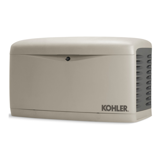
Kohler 14RESL 설치 매뉴얼 - 페이지 31
{카테고리_이름} Kohler 14RESL에 대한 설치 매뉴얼을 온라인으로 검색하거나 PDF를 다운로드하세요. Kohler 14RESL 48 페이지. Residential and light commercial generator sets
Kohler 14RESL에 대해서도 마찬가지입니다: 문제 해결 매뉴얼 (8 페이지)

1.14 Controller Configuration
The controller configuration for each generator model is
set at the factory and should not normally require
changes.
An authorized Kohler distributor/dealer can adjust the
RDC controller configuration and generator set
performance using the RDC controller keypad. Use the
select and arrow buttons to change settings or adjust
performance as described in the following sections.
Note: The DC controller cannot be adjusted from the
controller keypad.
An authorized Kohler distributor/dealer can adjust the
controller configuration and generator set performance
on both the RDC and DC controllers using Kohlerr
SiteTecht software and a personal computer. Contact
an authorized Kohler distributor/dealer for service.
Adjust the controller configuration with the generator set
off. Adjust the generator set performance with the
generator set running.
1
8
7
6
1. LED display
2. Up button
3. Select button
4. Down/Exercise button
Figure 1-29 RDC Residential Digital Control
TP-6733 8/11
2
3
4
5
5. Service access
6. RUN button and LED
7. AUTO button and LED
8. OFF button and LED
1.14.1 Firmware Version Number
To check the firmware version number on the RDC
controller, hold the select button and the up arrow button
for about 5 seconds, until the firmware version number
appears on the display. See Figure 1-31. On the DC
controller, the firmware version number is displayed
during the first 2 seconds of the engine start cycle.
The manufacturer may release new versions of
controller firmware. An authorized Kohlerr distributor or
dealer can update the controller firmware in the field.
Kohlerr SiteTecht software and a personal computer
are required.
See TP-6701, SiteTech Software
Operation maunal, for instructions.
1.14.2 System Parameters
The controller configuration for each generator model is
set at the factory and should not normally require
changes. The controller will display fault code NoEC (no
engine configuration setting) if the configuration is not
set.
The controller's configuration mode allows adjustment
of the system parameters listed in this section. Use the
instructions in this section to check the configuration
after installation and change it to match the settings
shown in Figure 1-30 for your application, if necessary.
An authorized distributor or dealer can use a personal
computer running Kohlerr SiteTecht software to set
the system parameters, if desired. The controller will
display Uu---- if the voltage and frequency are not set to
one of the standard combinations shown in Figure 1-30.
Parameter
Setting
System voltage
Uu01
and frequency *
Uu06
Uu07
Uu11
Uu15
Uu16
Uu19
Uu21
Uu22
Engine
Ec13
Configuration *
Ec14
* Factory-set for each model.
Figure 1-30 Controller Configuration Parameters
Definition
Phases
Hz
VAC
1
60
120/240
1
50
115/230
DO NOT USE
DO NOT USE
DO NOT USE
DO NOT USE
DO NOT USE
DO NOT USE
DO NOT USE
14RES/RESL
20RES/RESL
Section 1 Installation
31
