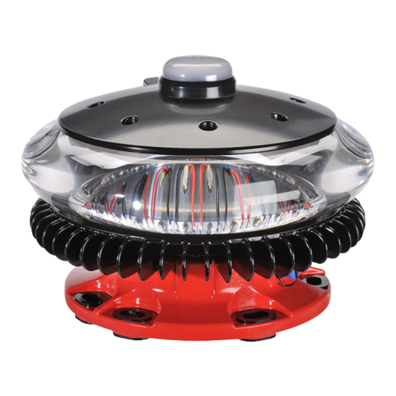
Avlite AV-OL-CMI 설치 및 서비스 매뉴얼 - 페이지 14
{카테고리_이름} Avlite AV-OL-CMI에 대한 설치 및 서비스 매뉴얼을 온라인으로 검색하거나 PDF를 다운로드하세요. Avlite AV-OL-CMI 20 페이지. Combined medium intensity obstruction light

General Purpose Inputs and Outputs
The AV-OL-CMI fixture supports a minimum of five discrete IOs via General Purpose Inputs (2) and Outputs (3) in order
to meet monitoring requirements as well as provide compatibility with our obstruction lighting controllers.
The I/O configurations must be specified at the time of order.
•
General Purpose Inputs (IN-1 and IN-2)
Available Input Type
Disabled
Photcell Control
OpMode Control
•
General Purpose Outputs (OUT-1 and OUT-2)
Available Output Type Description
Disabled
Photocell Status
LED Fault
Visible LED Fault
IR/NVR LED Fault
GPS Sync
7.3 Testing Procedure
Note: Avlite recommends that all testing be done during the day.
Check function of the MI by carrying out the following:
a.
Night mode test: Cover the CMI fixture and check night operation is functioning as described in the Day and Night
Time Operation Table below (depending on product type).
b. Day test mode: Uncover the CMI fixture and check day operation is functioning as described in the Day and Night
Time Operation table below (depending on product type).
Medium Intensity Obstruction Light
14
AV-OL-MI
Description
The input line will not be monitored.
The input line is used to control the state of the photocell/light sensor.
Input Low = Night
Input High = Day
The input line Is used to control the operation mode used by the lantern.
Input Low = Always On
Input High = Day and Night
The output line will remain inactive
The output line will show the status of the photocell/light sensor.
Open Contact = Night
Closed Contact = Day
The output line will show the fault state of the LED monitoring.
Open Contact = Fault
Closed Contact = OK
The output line will show the state of the GPS synchronisation.
Open Contact = Not Synchronised
Closed Contact = Synchronised
