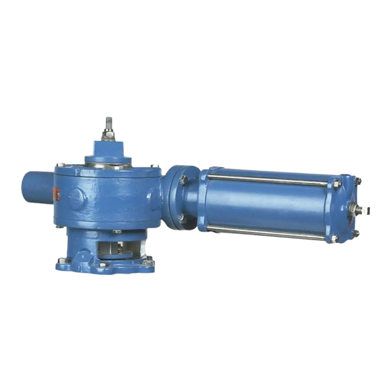
MANUAL G-SERIES ACTUATORS FOR USE WITH PTW & PFW TAPERED PLUG VALVES
Bearing and Seal Replacement
7. Remove the cover screws and cover from the actuator.
Note: It may be necessary to drive a chisel between the cover and actuator housing to loosen
the cover.
8. Lift the gear sector out of the actuator.
9. Remove the screws fastening the adaptor to the adaptor plate (2" the 4" valves) or to the valve
bonnet (5" thru 16" valves), then lift the actuator and adaptor off the valve.
10. Remove the gear sector seals from the top cover and the adaptor.
11. Drive the bearings out of the top cover and the adaptor.
12. Scrape the old gasket material from the top cover and actuator housing.
13. Grease the new bearings, then press them into the top cover and the adaptor.
14. Grease the new seals and press them into the top cover and adaptor.
15. Line up the scribe marks made earlier, then fasten the adaptor to the valve.
16. Pack the gear sector teeth with Keystone Zeniplex-1 and slide the gear sector down the valve
stem.
17. Place a new gasket on the actuator housing, then fasten the cover in place.
18. Slide the bearing washer down the stud sticking out the top of the actuator, then screw the plug
adjusting nut down the stud until it touches the bearing washer.
19. Turn the plug adjusting nut clockwise until there is .010" clearance between the plug face and
the body seat. If the valve is used for paper stock, the clearance should be .030".
Note: The holes in the bearing washer must line up with the tapped holes in the top of the gear
sector.
20. Set the pointer on the bearing washer so it fits down over the plug adjusting nut, then turn it until
it is positioned as noted when the actuator was disassembled. Fasten the pointer to the gear
sector with the two shorter socket head screws.
21. Set the wrenching square on the pointer and fasten it to the gear sector with the four remaining
socket head screws.
22. Screw the nut on the stud until it contacts the wrenching square. Tighten the nut to lock the
assembly into place.
23. Check the stop settings and readjust if necessary. The correct adjustment procedure is
described in the STOP ADJUSMENTS Section of this Instruction.
24. Pipeline flow and pressure may now be restored.
August 2012
(continued)
Page 7
DeZURIK
D10192

