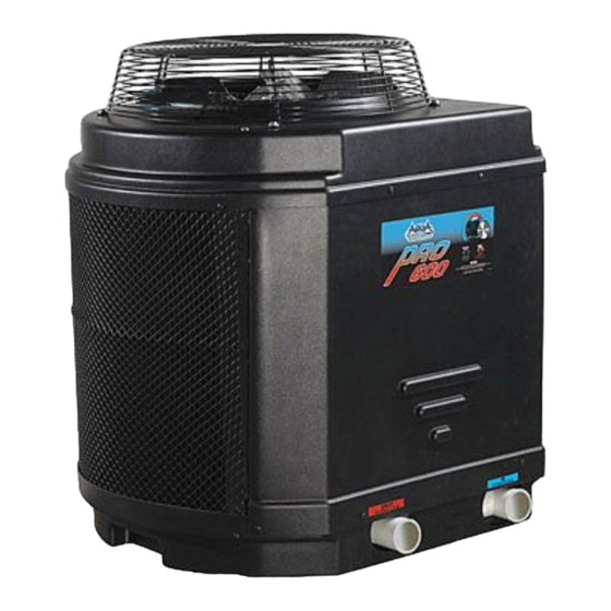
Aqua PRO PRO600 사용 설명서 - 페이지 2
{카테고리_이름} Aqua PRO PRO600에 대한 사용 설명서을 온라인으로 검색하거나 PDF를 다운로드하세요. Aqua PRO PRO600 13 페이지. Heat pump pool & spa heater

Operating Instructions
Installation
Procedures
Unit Inspection
Inspect your unit very carefully before
installing. Make sure there has been no
damage to the evaporator fins or there
are no punctures or oil-soaked areas
on the box. This would indicate
damage to the refrigeration system
and should be rejected immediately.
THE UNIT MUST BE TRANSPORTED
IN THE UPRIGHT POSITION AT ALL
TIMES AND MUST NOT BE DROPPED
OR TAILGATED. DAMAGE TO THE
UNIT DURING TRANSPORTATION IS
NOT THE RESPONSIBILITY OF THE
MANUFACTURER.
Unit Location
Once the unit has been inspected and
cleared of any transportation damage,
it is now time to locate the pool
heater. It is very important to
understand the location of the unit for
the best performance.
A minimum of 18" of clearance
between the evaporator coils and
shrubs, fences, walls, etc. must be
maintained for adequate air intake.
A minimum of 5' of vertical clearance
between the top of the unit and any
roof overhang or other obstructions
must be maintained in order to
prevent the re-circulation of cold air
back into the evaporator coils. This is
to maintain the efficiency of the unit.
A minimum of 24" of clearance
between the front of the unit (access
panel area) and any obstruction must
be maintained to allow maintenance
on the unit when necessary.
POOL
HEATER
Figure 1 - Recommended installation layout
www.aquaprosystems.com
The unit should be located on a solid
level surface, a minimum of 36"x 36"
for proper drainage.
Make sure any sprinkler heads are not
directly spraying water on the unit.
While heat pumps are made for an
outdoor environment, they are not
designed to have sprinkler water
constantly spraying them. NOTE: This
type of constant watering directly
on the unit can void your warranty.
Condensation drain holes are provided
in all units for adequate removal of
condensation and rainwater. ALL
UNITS WILL HAVE CONDENSATION.
THIS SHOULD NOT BE MISTAKEN
FOR A LEAK IN THE UNIT.
Plumbing
NOTICE
Where freezing weather is
encountered, the detachable
connection/union (NOT provided) must
be utilized immediately adjacent to the
heater to facilitate servicing and
draining of the heat exchanger.
Draining is necessary to prevent
damage to the condenser shell and
coil due to the expansion of
freezing water.
The minimum water circulation
capacity flowing through the pool
heater is 25 gallons per minute and the
maximum capacity is 80 gallons per
minute.
Do not install a water shutoff valve in
the piping from the outlet of the pool
heater to the pool or tub. However,
a check valve that does not include a
shut-off feature may be installed for
convenience during servicing.
A check valve or Hartford Loop is
recommended between the unit and
CHECK VALVE
2
a chlorinator. Failure to do so will void
the warranty.
Figure 1 shows the recommended
installation layout.
Basic Heat Pump
Operation
Electrical Connections
WARNING
!
connections must be performed by a
qualified electrician. Installations must
be in accordance with local and
national codes.
CAUTION
!
damage will result from inadequate
wiring.
All units are equipped with an
electrical wiring schematic inside the
electrical panel. If this is missing, please
contact the factory at 1-877-278-2797
to obtain one.
All units are to be wired for 230 VAC,
1 phase. This unit requires a dedicated
30-amp breaker or time delay fuse.
Pool Heater is to be installed in
accordance with Article 680 of the
National Electrical Code (NEC), NFPA
70, and within the requirements of all
local codes having jurisdiction.
Connecting to Remote
Systems
This Pool Heater is compatible with
2-wire remote systems. Figure 2 shows
where to connect the remote system to
the Temperature Controller.
FILTER
COLD WATER
IN FROM POOL
CHLORINATOR
WARM WATER
OUTLET TO POOL
All wiring and
electrical
Overheating, short-
circuiting and fire
