DFRobot TEL0051 매뉴얼 - 페이지 3
{카테고리_이름} DFRobot TEL0051에 대한 매뉴얼을 온라인으로 검색하거나 PDF를 다운로드하세요. DFRobot TEL0051 20 페이지. Gps/gprs/gsm module v3.0

14. 3. 2016
http://www.dfrobot.com/wiki/index.php/GPS/GPRS/GSM_Module_V3.0_(SKU:TEL0051)
GPS/GPRS/GSM Module V3.0 (SKU:TEL0051) Robot Wiki
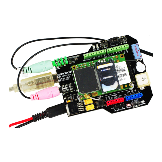
Earphone & Microphone
External power supply via the power jack
NOTE: It is recommended you to supply 712V@1A power via the power jack. When using
the GSM mode, the module requires an external power. But the power consumption is not
high,just 200mA@7v, when calling.
How to drive the GSM Mode via USB port
1. If your module is enabled, the indicator stat LED will light up, this means that the module is
running correctly. The LED marked "NET" will be lit when network communication has
being established.
2. Send the AT commands to the module by using Coolterm (http://freeware.the
meiers.org/CoolTermWin.zip)(or use the Arduino serial monitor).
NOTE: If you want to program the Arduino, please disconnect the coolterm to release the
communication port.
GSM mode & GPS mode Selection
Except using UART selection jumper caps(old version) or switch(latest version), you could switch
GSM and GPS function with the IO pins also. The UART selection is located on the bottom right
near the PWR STAT and NET LEDs. Remove the jumper caps connected for hardware UART
selection(old version) or set the switch in middle position(latest version) in order to control the
GSM / GPS by software.
Enable GPS mode & disable GSM mode:
?
1
2
Enable GSM mode & disable GPS mode:
?
1
2
NOTE: You could control GPS through the GSM AT commands, without requiring to enable
both independently. This way you can let the GPS enabled while using GSM network. Thus not
triggering a GPS reset.
Network indication
State
SIM908 behavior
Off
SIM908 is not running
64ms On/ 800ms Off SIM908 not registered the network
64ms On/ 3,000ms Off SIM908 registered to the network
64ms On/ 300ms Off PPS GPRS communication is established
NOTE: Following the steps included in the sketch below first!
3/20
