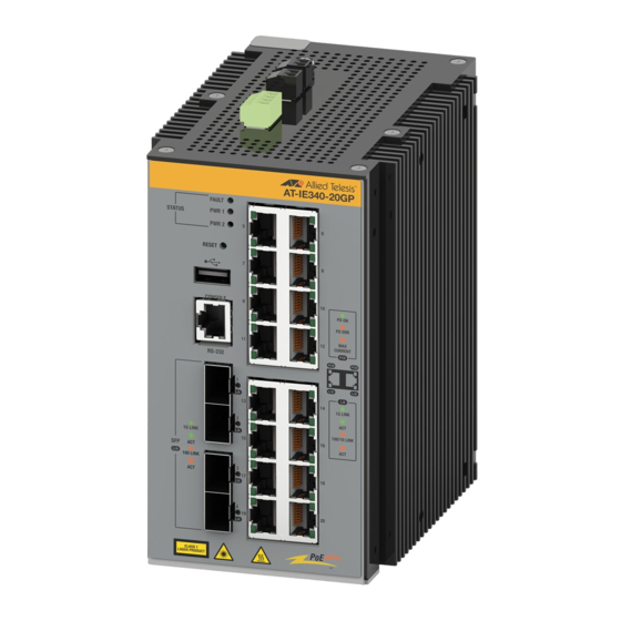
Allied Telesis IE340-12GP 빠른 설치 매뉴얼 - 페이지 3
{카테고리_이름} Allied Telesis IE340-12GP에 대한 빠른 설치 매뉴얼을 온라인으로 검색하거나 PDF를 다운로드하세요. Allied Telesis IE340-12GP 4 페이지. Industrial ethernet layer 3 switches
Allied Telesis IE340-12GP에 대해서도 마찬가지입니다: 빠른 설치 매뉴얼 (2 페이지)

8. Secure the grounding wire to the IE340 Switch with the grounding screw.
9. Connect the other end of the grounding wire to a ground point at the installation site.
Preparing the DC Power Cables
The switch can be powered by one or two DC power supplies. Two power supplies
provide power redundancy.
Each power supply is connected to the switch with two wires, one positive (+) and one
negative (-). If you are installing only one power supply to the switch, you may connect it
to either the PWR1 or PWR2 connector. For the power requirements, refer to Appendix
A, Technical Specifications, in the IE340 Series Installation Guide.
To build DC power cables for the unit, perform the following procedure:
1. Strip 6.5mm (0.25 in.) of insulation from the ends of two strand power wires
(recommended 18 AWG) with a wire insulator stripper.
6.5mm (0.25 in.)
2. Tightly wrap the wire strands with your finger tips.
Note
Allied Telesis recommends tinning the wires with solder as added protection against
loose strands.
3. Remove the PWR 1 - PWR 2 connector from the top panel.
4. Loosen the wire retaining screws in the connector with a #1 screwdriver.
5. Insert the wires into the connector and tighten the retaining screws to secure the wires.
6. After attaching the wires to the connector, verify that there are no exposed wires or
loose wire strands.
Exposed
Correct
Wire
7
Powering on the Switch
1. Verify that the DC power supply is powered off. If there are two DC power supplies,
verify that both units are powered off.
2. Connect the DC input plug to the Power connector on the front panel.
3. Connect the other end of the power cables to the DC power supplies.
4. Power on the DC power supplies.
5. Wait three to four minutes for the switch to start its operating system.
Starting the First Management Session
This section explains how to start a local management session through the Console port on
the switch. This procedure requires a terminal, computer, or laptop with an RS-232 serial
port or USB port, and terminal emulator, such as PuTTy. It also requires a management
cable, as follows:
If your computer has an RS-232 port, you may use the supplied management cable or
refer to Appendix A, Technical Specifications, in the IE340 Series Installation Guide for
cable wiring specifications.
If your computer has a USB port, you may need to purchase a USB-to-Serial converter
that is compatible with its operating system. An example is the VT-Kit3 converter from
Allied Telesis.
Note
The first management session with the switch can also be over the Ethernet
network through any of the copper or SFP+ ports. The switch has both DHCPv4 and
DHCPv6 clients. Their default state is enabled. If the switch does not receive a
response from a DHCP server, it uses the default address 169.254.42.42/16.
To start a local management session, perform the following procedure:
1. Connect your computer to the Console port on the switch with a serial cable or the VT-
Loose
Kit3, (If you are using the VT-Kit3, refer to the IE340 Series Installation Guide for
Strands
instructions.)
2. Configure your terminal emulation program as follows:
Baud rate: 9600 bps (The baud rate of the Console port is adjustable from 1200 to
115200 bps. The default is 9600 bps.)
Data bits: 8
Parity: None
Stop bits: 1
Flow control: None
3. Press Enter. You are prompted for the name and password of the manager account.
4. Enter the user name and password. They are case-sensitive. The default values are:
User name: manager
Password: friend
8
9
