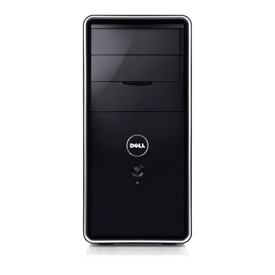
Dell DCME 서비스 매뉴얼 - 페이지 24
{카테고리_이름} Dell DCME에 대한 서비스 매뉴얼을 온라인으로 검색하거나 PDF를 다운로드하세요. Dell DCME 45 페이지. Service manual

Back to Contents Page
Front I/O Panel
Dell™ Inspiron™ 560/570 Service Manual
Removing the Front I/O Panel
Replacing the Front I/O Panel
WARNING:
Before working inside your computer, read the safety information that shipped with your computer. For additional safety best
practices information, see the Regulatory Compliance Homepage at www.dell.com/regulatory_compliance.
WARNING:
To guard against electrical shock, always unplug your computer from the electrical outlet before removing the cover.
WARNING:
Do not operate your equipment with any cover(s) (including computer covers, bezels, filler brackets, front-panel inserts, etc.)
removed.
CAUTION:
Only a certified service technician should perform repairs on your computer. Damage due to servicing that is not authorized by Dell™
is not covered by your warranty.
Removing the Front I/O Panel
1. Follow the procedures in
Before You
2. Remove the computer cover (see
3. Remove the front bezel (see
CAUTION:
When sliding the front I/O panel out of the computer, be extremely careful. Carelessness may result in damage to the cable
connectors and the cable routing clips.
4. Disconnect all the cables that are connected to the front I/O panel from the system board connectors. Note the routing of all cables as you remove them
so that you can re-route them correctly after installing the new front I/O panel.
5. Remove the screw that secures the front I/O panel to the chassis.
6. Carefully slide the front I/O panel down and out of the front I/O panel clamp slot.
1 front I/O panel clamp slot 2 cables 3 front I/O panel clamp
4 front I/O panel
5 screw
Replacing the Front I/O Panel
CAUTION:
Take care not to damage the cable connectors and the cable routing clips when sliding the front I/O panel into the front I/O panel
clamp slot.
1. Follow the procedures in
Before You
2. Route and connect the cables that you disconnected from the system board connectors.
3. Align and slide the front I/O panel clamp into the front I/O panel clamp slot.
4. Replace the screw that secures the front I/O panel to the chassis.
Begin.
Removing the Computer
Cover).
Removing the Front
Bezel).
Begin.
