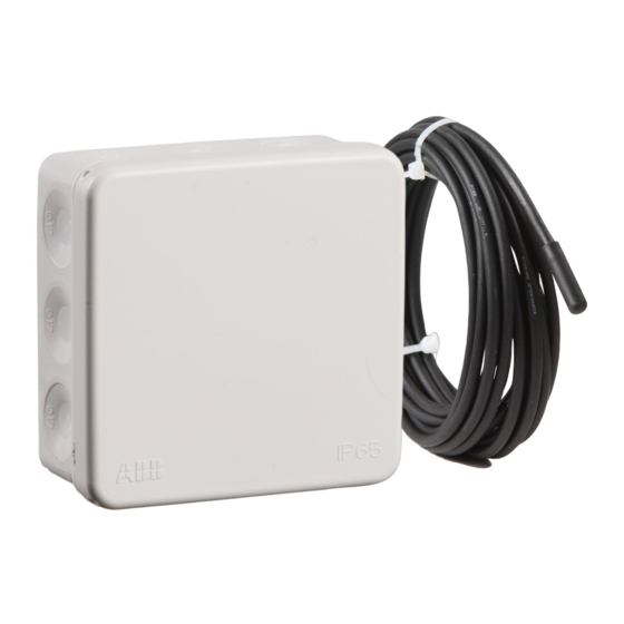
ensto ECO500 설치 및 운영 지침 매뉴얼 - 페이지 5
{카테고리_이름} ensto ECO500에 대한 설치 및 운영 지침 매뉴얼을 온라인으로 검색하거나 PDF를 다운로드하세요. ensto ECO500 16 페이지. Frost protection thermostat
ensto ECO500에 대해서도 마찬가지입니다: 작동 지침 (4 페이지)

ENG
ECO500 Frost protection thermostat
Installation and Operating Instructions
ECO500 is an electronic thermostat for frost protection of drain pipes.
1. Safety Instructions
Electrically skilled person
•
The installation must only be done by an electrician with the appropriate qualifications.
•
Follow the instructions in this manual, and make sure that the installation complies with national
safety regulations, installation methods and restrictions.
•
The information provided in this manual in no way exempts the installer or user from responsibil-
ity to follow all applicable safety regulations.
•
Keep this manual for future installation and service.
WARNING
Danger of electric shock! Risk of fire!
•
Disconnect the power supply before carrying out any installation or maintenance work on this
thermostat and associated components.
•
Do not switch on the power supply before the installation work is completed.
•
Improper installation can cause personal injury and property damage.
•
Do not operate a defect thermostat.
2. Installation Instructions
•
Install the thermostat in accordance with figures 1 and 2.
•
Attach the sensor outside the pipe on the opposite side of the heating cable, and in such a manner that
it measures the coldest spot of the pipe.
•
A residual circuit breaker must be used in accordance with the local installation regulations.
3. User Instructions
•
Set the temperature by turning the adjustment wheel, figure 1.
Switch off the power before you remove the thermostat cover!
4. Warranty
•
The warranty period for Ensto ECO thermostats is 2 years from the date of purchase but no longer than
3 years from the date of manufacture. Warranty conditions, see
5. Disposal
Do not dispose of electrical and electronic devices including their accessories with the household
waste.
The product's cardboard packing is suitable for recycling.
When a heating system is at the end of the life cycle the cables, conduits and electronic components must
be disposed of properly according to local recycling guidelines.
6. Technical Data
Rated voltage
Adjustment range
Load (max)
Nominal current
Sensor
Sensor resistance values
Ambient temperature (t
Ingress protection
230V/50Hz, -15%/+10%
+2 ... +35 ºC
3600W, 16A cosφ = 1 / 2A cosφ = 0,4
16A
NTC / cable 4m, extendable, max 50m (2 x 1,5 mm
Table on page 2 (sensor is not connected)
)
-30 ... +30 ºC
a
IP55
RAK59 / 2023-03-15
www.ensto.com/building-systems
)
2
5 / 16
