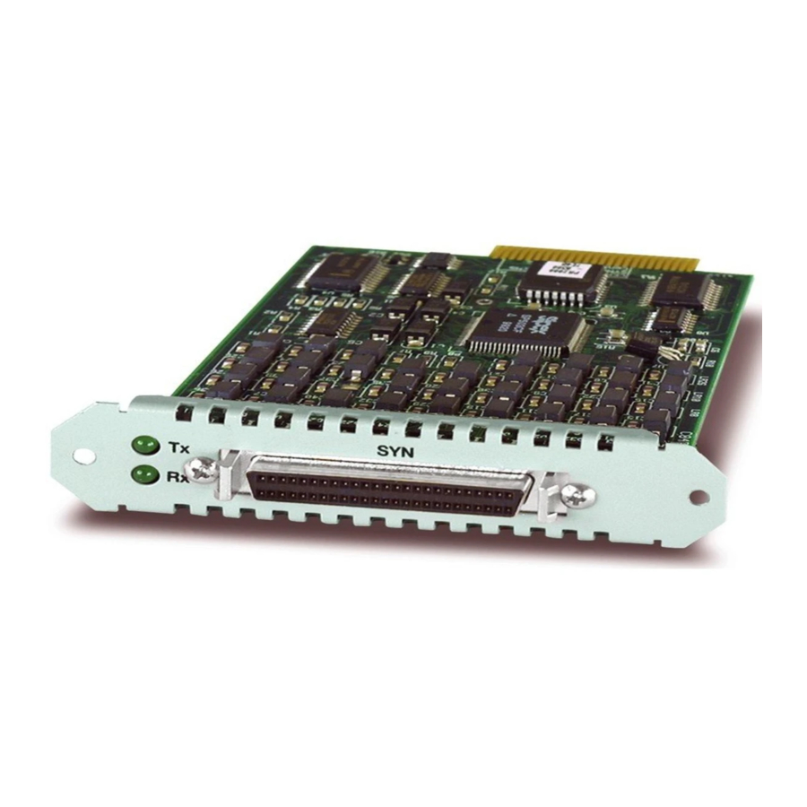
Allied Telesis AT-AR020 PRI E1/T1 빠른 설치 매뉴얼 - 페이지 4
{카테고리_이름} Allied Telesis AT-AR020 PRI E1/T1에 대한 빠른 설치 매뉴얼을 온라인으로 검색하거나 PDF를 다운로드하세요. Allied Telesis AT-AR020 PRI E1/T1 10 페이지. Port interface card
Allied Telesis AT-AR020 PRI E1/T1에 대해서도 마찬가지입니다: 설치 매뉴얼 (13 페이지), 설치 매뉴얼 (13 페이지), 데이터시트 (1 페이지), 설치 및 안전 매뉴얼 (8 페이지)

4
Figure 1: An AT-AR40 NSM (with 3 PICs) installed in an AR824.
These PICs, PICs installed directly into routers (i.e., PICs not installed in an
AR040 NSM), or PICs installed in any device running Software Release 2.2.3 or
earlier must be installed or removed using the Standard Method (as outlined
below).
To find out which software release your switch or router is running, use the
command:
SHOW RELEASE
Installing A PIC
Standard Installation Method:
1.
Read the safety information
For safety information, see the Safety and Statutory Information booklet for
your switch or router. A copy of this booklet can be found on the CD-ROM
that came with your switch or router, or at www.alliedtelesyn.co.nz/
support/support.html.
2.
Gather the tools and equipment you will need
A medium-sized flat-bladed screwdriver may be useful when loosening
the PIC thumbscrews.
You should also have any cables required for connecting the PIC to a wide
area network or other network devices.
3.
For switches and routers with NSM bays, check that an NSM
is installed
AR800 Series Switching Routers and Rapier Switches require an AT-AR040
NSM to be installed before PICs can be installed. AR740 and AR745
Routers have two base-unit PIC bays; installing an AT-AR040 NSM
provides four additional PIC bays.
NSMs are installed in the rear panel of AR800 Series Switching Routers,
Rapier Switches, AR740 Routers, and AR745 Routers (see Figure 1 on
page -4).
AT-AR022 ETH PICs and AT-AR026 4ETH PICs are not recommended for use in
AT-AR040 NSM PIC bays.
SYN
Tx
Rx
NSM with 3 PICs
4.
If connected, disconnect the switch or router from its redundant power supply
3
0
D Data
Active
B Data
N
Port Interface Card
C613-04020-01 REV H
