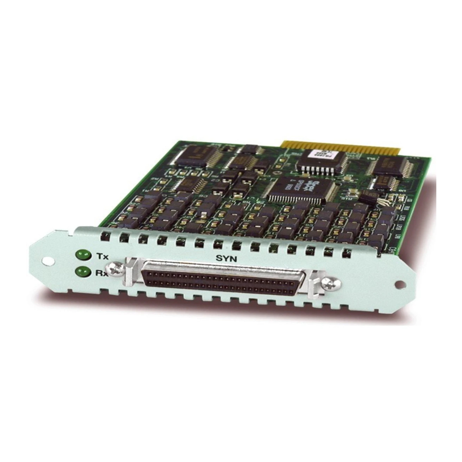
Allied Telesis AT-AR021 (S) BRI-S/T 빠른 설치 매뉴얼 - 페이지 5
{카테고리_이름} Allied Telesis AT-AR021 (S) BRI-S/T에 대한 빠른 설치 매뉴얼을 온라인으로 검색하거나 PDF를 다운로드하세요. Allied Telesis AT-AR021 (S) BRI-S/T 10 페이지. Port interface card
Allied Telesis AT-AR021 (S) BRI-S/T에 대해서도 마찬가지입니다: 설치 매뉴얼 (13 페이지), 설치 매뉴얼 (13 페이지), 설치 및 안전 매뉴얼 (8 페이지)

Quick Install Guide
C613-04020-01 REV H
5.
Disconnect the switch or router from its AC or DC power supply
When using the Standard Installation method, be sure to disconnect the main
power supply and the redundant power supply before installing a PIC.
Installing a PIC with the switch or router powered ON can damage the PIC.
6.
Remove the PIC-bay face-plate, NSM PIC-bay face-plate, or existing PIC
Loosen the thumbscrews to remove the face-plate or PIC.
Keep the face-plate for future use. If you remove the PIC, replace the face-plate to prevent
dust and debris from entering the switch or router and to maintain proper airflow.
7.
Unpack the PIC
In an antistatic environment, remove the PIC from its packing material. Be
sure to observe ESD precautions.
Do not attempt to install a PIC or any other expansion option without
observing correct antistatic procedures. Failure to do so may damage the switch
or router, PIC, or expansion option. If you are unsure what the correct
procedures are, contact your authorised Allied Telesyn distributor or reseller.
8.
If the PIC has jumpers, check they are correctly set
AT-AR020 PRI E1/T1 and AT-AR021(S) BRI-S/T PICs have user-
configurable jumpers. Check all jumpers and other hardware
configurations are set correctly on the new PIC (see Table 1 and Table 2).
AT-AR026 4ETH PICs have user-configurable links that set features such as
auto-negotiation, buffer size, and MAC address aging. Descriptions of the
links can be found in the PIC Hardware Reference.
Table 1: Functions of jumpers on the AT-AR020 PRI E1/T1 PIC board.
Jumper
Function
J1
Selects ISDN NT mode (installed, test only) or TE mode (not
installed).
J2
Selects T1 mode (installed) or E1 mode (not installed).
Earlier versions of the AT-AR020 PIC also have a J3 interface jumper. If present, this
jumper must be installed for E1 mode and removed for T1 mode.
Table 2: Functions of jumpers on the AT-AR021(S) BRI-S/T PIC board.
Jumper
Function
J1
100Ω termination for TX.
J2
100Ω termination for RX.
5
Default
Not installed.
Not installed.
